


Installation Guide
59
5.3
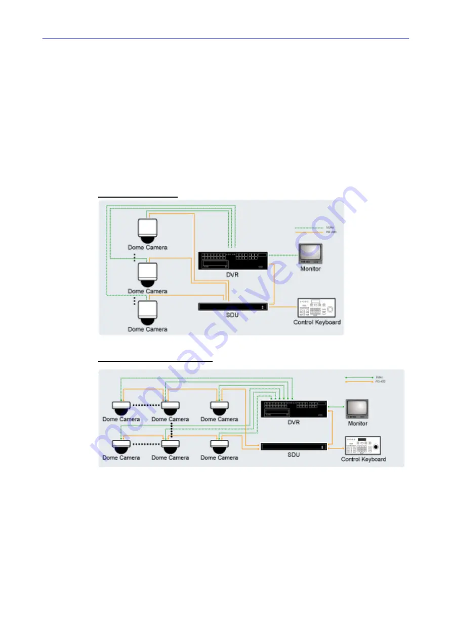
Signal Distribution Unit
The RS-485 Signal Distribution Unit (SDU) is designed to relay control codes
to Speed Dome Cameras. It is capable of communicating with cameras up to
1.0 kilometers away. Additionally, the SDU can be installed in either “star” or
“daisy chain” configuration with up to 160 cameras (see the diagrams below).
Its versatile installation configuration makes an easy integration into
expanding surveillance systems. For more information, please refer to the
SDU user’s manual.
Star Configuration
Daisy Chain Configuration