background image

California, U.S. EPA, and Briggs & Stratton Corporation Emissions Control Warranty Statement

Your Warranty Rights And Obligations

September 2012

The California Air Resources Board, U.S. EPA, and Briggs & Stratton (B&S) are pleased

to explain the emissions control system warranty on your Model Year 2012--2013

engine/equipment. In California, new small off-road engines and large spark ignited

engines less than or equal to 1.0 liter must be designed, built, and equipped to meet the

State’s stringent anti-smog standards. B&S must warrant the emissions control system

on your engine/equipment for the periods of time listed below provided there has been

no abuse, neglect, or improper maintenance of your engine or equipment.
Your emissions control system may include parts such as the carburetor or fuel injection

system, fuel tank, ignition system, and catalytic converter. Also included may be hoses,

belts, connectors, sensors, and other emissions-related assemblies.
Where a warrantable condition exists, B&S will repair your engine/equipment at no cost

to you including diagnosis, parts, and labor.

Manufacturer’s Warranty Coverage:

Small off-road engines and large spark ignited engines less than or equal to 1.0 liter, and

any related emissions components of the equipment, are warranted for two years*. If any

emissions-related part on your B&S engine/equipment is defective, the part will be

repaired or replaced by B&S.
*

Two years or for the time period listed in the respective engine or product warranty

statement, whichever is greater.

Owner’s Warranty Responsibilities:

As the engine/equipment owner, you are responsible for the performance of the

required maintenance listed in your owner’s manual. B&S recommends that you

retain all receipts covering maintenance on your engine/equipment, but B&S cannot

deny warranty solely for the lack of receipts or your failure to ensure the performance

of all scheduled maintenance.

As the engine/equipment owner, you should however be aware that B&S may deny

you warranty coverage if your engine/equipment or a part has failed due to abuse,

neglect, improper maintenance, or unapproved modifications.

You are responsible for presenting your engine/equipment to a B&S distribution

center, servicing dealer, or other equivalent entity, as applicable, as soon as a

problem exists. The warranty repairs should be completed in a reasonable amount of

time, not to exceed 30 days. If you have any questions regarding your warranty

rights and responsibilities, you should contact B&S at (414) 259-5262.

Briggs & Stratton Emissions Control Warranty Provisions

The following are specific provisions relative to your Emissions Control Warranty Coverage. It is in addition to the B&S engine warranty for non-regulated engines found in the

Operator’s Manual.
1.

Warranted Emissions Parts
Coverage under this warranty extends only to the parts listed below (the emissions

control systems parts) to the extent these parts were present on the B&S engine

and/or B&S supplied fuel system.
a.

Fuel Metering System

Cold start enrichment system (soft choke)

Carburetor and internal parts

Fuel pump

Fuel line, fuel line fittings, clamps

Fuel tank, cap and tether

Carbon canister

b.

Air Induction System

Air cleaner

Intake manifold

Purge and vent line

c.

Ignition System

Spark plug(s)

Magneto ignition system

d.

Catalyst System

Catalytic converter

Exhaust manifold

Air injection system or pulse valve

e.

Miscellaneous Items Used in Above Systems

Vacuum, temperature, position, time sensitive valves and switches

Connectors and assemblies

2.

Length of Coverage
For a period of two years from date of original purchase, B&S warrants to the original

purchaser and each subsequent purchaser that the engine is designed, built, and

equipped so as to conform with all applicable regulations adopted by the Air

Resources Board; that it is free from defects in material and workmanship that could

cause the failure of a warranted part; and that it is identical in all material respects to

the engine described in the manufacturer’s application for certification. The warranty

period begins on the date the engine is originally purchased.

The warranty on emissions-related parts is as follows:

Any warranted part that is not scheduled for replacement as required

maintenance in the owner’s manual supplied, is warranted for the warranty

period stated above. If any such part fails during the period of warranty

coverage, the part will be repaired or replaced by B&S at no charge to the

owner. Any such part repaired or replaced under the warranty will be warranted

for the remaining warranty period.

Any warranted part that is scheduled only for regular inspection in the owner’s

manual supplied, is warranted for the warranty period stated above. Any such

part repaired or replaced under warranty will be warranted for the remaining

warranty period.

Any warranted part that is scheduled for replacement as required maintenance

in the owner’s manual supplied, is warranted for the period of time prior to the

first scheduled replacement point for that part. If the part fails prior to the first

scheduled replacement, the part will be repaired or replaced by B&S at no

charge to the owner. Any such part repaired or replaced under warranty will be

warranted for the remainder of the period prior to the first scheduled

replacement point for the part.

Add on or modified parts that are not exempted by the Air Resources Board

may not be used. The use of any non exempted add on or modified parts by the

owner will be grounds for disallowing a warranty claim. The manufacturer will

not be liable to warrant failures of warranted parts caused by the use of a non

exempted add on or modified part.

3.

Consequential Coverage

Coverage shall extend to the failure of any engine components caused by the

failure of any warranted emissions parts.

4.

Claims and Coverage Exclusions

Warranty claims shall be filed according to the provisions of the B&S engine

warranty policy. Warranty coverage does not apply to failures of emissions parts

that are not original equipment B&S parts or to parts that fail due to abuse, neglect,

or improper maintenance as set forth in the B&S engine warranty policy. B&S is not

liable for warranty coverage of failures of emissions parts caused by the use of

add-on or modified parts.

Look For Relevant Emissions Durability Period and Air Index Information

On Your Small Off-Road Engine Emissions Label

Engines that are certified to meet the California Air Resources Board (CARB) small

off-road Emissions Standard must display information regarding the Emissions Durability

Period and the Air Index. Briggs & Stratton makes this information available to the

consumer on our emissions labels. The engine emissions label will indicate certification

information.
The

Emissions Durability Period

describes the number of hours of actual running time

for which the engine is certified to be emissions compliant, assuming proper

maintenance in accordance with the Operating & Maintenance Instructions. The

following categories are used:

Moderate:

Engine is certified to be emissions compliant for 125 hours of actual engine running time.

Intermediate:

Engine is certified to be emissions compliant for 250 hours of actual engine running time.

Extended:

Engine is certified to be emissions compliant for 500 hours of actual engine running time.

For example, a typical walk-behind lawn mower is used 20 to 25 hours per year.

Therefore, the

Emissions Durability Period

of an engine with an

intermediate

rating

would equate to 10 to 12 years.

Briggs & Stratton engines are certified to meet the United States Environmental

Protection Agency (USEPA) Phase 2 or Phase 3 emissions standards. The Emissions

Compliance Period referred to on the Emissions Compliance label indicates the number

of operating hours for which the engine has been shown to meet Federal emissions

requirements.

For engines less than 225 cc displacement.

Category C = 125 hours, Category B = 250 hours, Category A = 500 hours

For engines of 225 cc or more displacement.

Category C = 250 hours, Category B = 500 hours, Category A = 1000 hours

Not 

for  

Reproduction

Summary of Contents for SW20 Series

Page 1: ...S STRATTON POWER PRODUCTS GROUP LLC 5375 NORTH MAIN STREET MUNNSVILLE NY 13409 800 933 6175 5101263 Rev H Model Number Description 5900700 SW20KAV1748 48 Cut Walk Behind Mower 5900702 SW20KAV1336 36 C...

Page 2: ...ct We re pleased that you ve placed your confidence in the SNAPPER PRO brand When operated and maintained according to the instructions in this manual your SNAPPER PRO product will provide many years...

Page 3: ...er Change 22 Lubrication 23 Check Fill Transmission Oil 24 Transmission Oil Filter Change 24 Servicing the Mower Blades 25 Neutral Adjustment 27 Speed Balancing Adjustment S N 2014523387 Below 27 S N...

Page 4: ...sen ask a professional contact your local authorized dealer Read the Manual The operator s manual contains important safety information you need to be aware of BEFORE you operate your unit as well as...

Page 5: ...be thrown by the blade BEFORE you start mowing Do not operate this unit without the entire grass catcher or discharge guard deflector in place Also do not allow anyone in the area while the unit is ru...

Page 6: ...oke while operating or refueling Do not add fuel while engine is hot or running Allow engine to cool for at least 3 minutes prior to adding fuel Do not add fuel indoors in an enclosed trailer garage o...

Page 7: ...loading or unloading the machine into a trailer or truck TRAINING 1 Read understand and follow all instructions in the manual and on the unit before starting If the operator s or mechanic s can not r...

Page 8: ...on steep slopes CHILDREN Tragic accidents can occur if the operator is not alert to the presence of children Children are often attracted to the unit and the mowing activity Never assume that childre...

Page 9: ...o stop before adjusting cleaning or repairing 9 Clean grass and debris from cutting units drives mufflers and engine to prevent fires Clean up oil or fuel spillage 10 Let engine cool before storing an...

Page 10: ...the safety decals The cautions and warnings are for your safety To avoid a personal injury or damage to the unit understand and follow all safety decals WARNING If any safety decals become worn or dam...

Page 11: ...n the NEUTRAL position and the operator must engage the operator presence handles in order to start the engine Safety Icons The alert symbol is used to identity safety information about hazards that c...

Page 12: ...E Compliance Logo F Year of Manufacture G Maximum Engine Speed in Rotations Per Minute H Power Rating in Kilowatts I Mass of Unit in Kilograms J Sound Power in Decibels This unit complies with Europea...

Page 13: ...ols the forward ground speed of both drive wheels The left reverse speed control lever controls the steering and reverse ground speed of the left drive wheel The right reverse speed control lever cont...

Page 14: ...ke ENGAGE Locks the parking brake Pull the parking brake handle up to engage the parking brake Push the parking brake handle down to disengage the parking brake NOTE To start the unit the parking brak...

Page 15: ...s Before Starting Check that crankcase is filled to full mark on the engine oil dipstick B Figure 3 See the engine Operator s Manual for instructions and oil recommendations Fill the fuel tank A with...

Page 16: ...pulling the transmission release levers rearward and inward to release them from the disengaged position and then allow them to move to the engaged drive position Figure 5 Transmission Release Levers...

Page 17: ...p 4 See Figure 8 If you are adjusting the cutting height range between 1 1 2 3 8 cm and 2 3 4 6 9 cm position the belt in the lower pulley on PTO clutch If you are adjusting the cutting height range b...

Page 18: ...ISE to lower the deck to the desired cutting height After the desired cutting heights are achieved position the cutting height adjustment handles into the handle lock position 2 Repeat the process for...

Page 19: ...forward until desired speed is achieved To Move Backward 1 Disengage the parking brake 2 Gently squeeze both reverse speed control levers B evenly until desired speed is achieved To Slow or Stop Mach...

Page 20: ...fe of your machine Height of Grass Often cutting height is a matter of personal preference Typically you should mow the grass when it is is between three and five inches high The proper cutting height...

Page 21: ...will improve the cutting efficiency of the blades and prevents many common cutting problems Use an appropriate ground speed for the thickness and height of the grass you are cutting 3rd gear or slower...

Page 22: ...dcasting side discharging or grass bagging operation Engine Speed Ground Speed for Mulching Use full engine throttle matched with a slow ground speed so that clippings will be finely cut Ground speed...

Page 23: ...100 Hours Every 200 Hours Spring Fall Check Unit for Loose Hardware Clean Deck Check Replace Mower Blades Lubricate Mower Mower Deck Check Tire Pressure Check Hydraulic Oil Change Hydraulic Oil Filte...

Page 24: ...engine oil filter C Remove the engine oil filter and replace with a new one 6 Remove the oil dipstick D and refill with oil Refer to the engine operator s manual for oil recommendations 7 Remove the...

Page 25: ...pedal pivots Figure 14 Front Caster Wheel A 1 4 28 Bolt A Generally all moving metal parts should be oiled where contact is made with other parts Keep oil and grease off belts and pulleys Remember to...

Page 26: ...new filter onto the filter base until the gasket makes contact then tighten 3 4 of a turn more 5 Reinstall the filter guard with the three 1 4 filter guard screws 6 Using a hex bit swivel socket or a...

Page 27: ...harp or have nicks sharpen the blades See Sharpening the Mower Blades Figure 17 Loosening the Mower Blade for Removal Figure 18 inspecting the Mower Blade Tips A Mower Blade Cutting Edge B Square Corn...

Page 28: ...zontal position Reinstalling the Mower Blades 1 Reinstall each mower blade with the air lifts pointing up towards the mower deck as shown in Figure 22 Secure with the mower blade mounting bolt and fla...

Page 29: ...ved NOTE This adjustment should not be performed while the machine is running It may take several attempts to achieved neutral depending upon how much the machine creeps Speed Balancing Adjustment 201...

Page 30: ...sed together to turn the rod and the third is used to lock the rod in place 1 Loosen the jam nut that locks against the clevis 2 Turn the linkage rod COUNTER CLOCKWISE to reduce the speed 3 Retighten...

Page 31: ...he rear of the machine 3 With the parking brake engaged measure the compressed spring length of the brake spring The spring should be 2 3 8 6 03 cm when compressed If not position the lock nut until t...

Page 32: ...st the deck to the 3 7 6 cm position 3 Repeat process for other side of machine NOTE Both sides of the deck must be adjusted to the same height 4 Place 2 x 4 blocks under the rear of the mower deck wi...

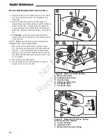
Page 33: ...he belt exerted from the idler arm 4 Slide the mower drive belt over the edge of the stationary idler pulley C Carefully release the tension on the breaker bar Figure 29 Remove the Mower Belt A Breake...

Page 34: ...stationary pulley C Figure 29 Carefully rotate the breaker bar counter clockwise and install the belt on the stationary idler pulley Carefully release the tension on the breaker bar 7 36 Models Using...

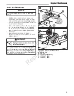
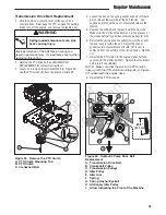
Page 35: ...o completely release the tension 5 Remove the old belt and replace it with the new one Make sure the V side of the belt runs in the grooves of the crankshaft pulley and transmission pulleys B C 6 Rein...

Page 36: ...pressure to depress both handles Handle Placement Adjustment Later Models Only There should be approximately 1 2 54 cm fo clearance in between the handle bars and the reverse speed control levers whe...

Page 37: ...left in unit disconnect the negative cable 10 Drain fuel system completely or add a gasoline stabilizer to the fuel system If you have chosen to use a fuel stabilizer and have not drained the fuel sy...

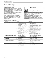
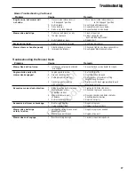
Page 38: ...8 Spark plug s faulty fouled 11 Clean and gap or replace or incorrectly gapped See engine manual 9 Water in fuel 12 Drain fuel replace with fresh fuel 10 Gas is old or stale 13 Drain fuel replace with...

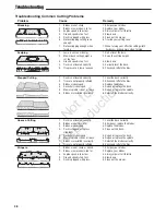
Page 39: ...d 1 See authorized service dealer for repair or damaged Engine stalls easily with 1 Engine speed too slow 1 Set to full throttle mower deck engaged 2 Ground speed too fast 2 Decrease Ground Speed 3 Cu...

Page 40: ...tly 2 Tires are not properly inflated 2 Check and inflate the tires 3 Blades are damaged 3 Replace the blades 4 Deck shell is damaged 4 Repair or replace the deck 5 Mower spindle is bent or loose 5 Re...

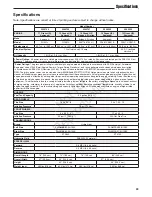
Page 41: ...and air cleaner installed whereas gross power values are collected without these attachments Actual gross engine power will be higher than net engine power and is affected by among other things ambie...

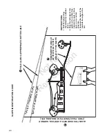
Page 42: ...e pole a fence post or any vertical structure 3 Compare the angle of the fold with the angle of the hill SLOPE INDENTIFICATION GUIDE ALIGN THIS EDGE WITH A VERTICAL SURFACE TREE POLE FENCE POST BUILDI...

Page 43: ...Notes N o t f o r R e p r o d u c t i o n...

Page 44: ...Notes N o t f o r R e p r o d u c t i o n...

Page 45: ...N o t f o r R e p r o d u c t i o n...

Page 46: ...ize to you for being inconvenienced Warranty service is available only through SNAPPER PRO Authorized Service Dealers Most warranty repairs are handled routinely but sometimes requests for warranty se...

Page 47: ...respects to the engine described in the manufacturer s application for certification The warranty period begins on the date the engine is originally purchased The warranty on emissions related parts...

Page 48: ...Operator s Manual SW20 Series Walk Behind Mowers BRIGGS STRATTON POWER PRODUCTS GROUP LLC 5375 NORTH MAIN STREET MUNNSVILLE NY 13409 800 933 6175 N o t f o r R e p r o d u c t i o n...

Reviews: