background image

21

ENSAMBLA

NOMBRE DE

FIGURA

QTD

60V


La Pieza

1

Tubo del 

ventilador

1

60V 2.5Ah Batería

1

60V Cargador

1

Manual de

instrucciones

Please do not return product to retailer.

Porf avor,n od evuelva el producto al lugard ec ompra.

Veuillez ne pasr etourner le produita ud étaillant.

1-800-317-7833

www.snapper.com

WARNING:

ADVERTENCIA:

AVERTISSEMENT:

Lire le manuel d’instructions et bien respectert ousl es avertisse-

mentse tt outesl es instructions de sécurité.Toutdé fautde le fa ire

pourrait entraînerd es blessuresg raves.

L O

Ñ

A P

S E

H S

I L

G

N E

FR

AN

ÇA

IS

Briggs & Stratton Power Products Group, LLC

Milwaukee, WI, USA

InstructionM anual

Manuald eI nstrucciones

Manueld ’Instructions

Read and follow all Safety Rules and Operating Instructions before 

using this product. Failure to do so can result in serious injury.

Lea el manual de instrucciones y siga todas las advertencias e

instrucciones de seguridad. El no hacerlo puede resultar en

lesiones graves.


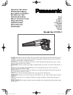
60V LITHIUM-ION

CORDLESS STRING TRIMMER

Model ST60V

Rev. 00 07/30/15

1

Guía para

comienzo

rápido

QUICK START GUIDE

60V LITHIUM-ION

BRUSHLESS STRING TRIMMER

ST60V

ATTACHING THE GUARD

Missing parts, accessories or need a service center? 

Do Not Return to Store

Call: 1-800-317-7833   www.snapper.com

1. Invert the string trimmer to access the 

trimmer head. 

2. Remove supplied screws (1) from the 

trimmer head (4) with a philips 

screwdriver (not included).

3. Place the guard (2) on to the trimmer 

head.

4. Align the screw holes (3) on the guard 

with the screw holes on the trimmer head.

5. Insert the screws into the trimmer 

head, fastening the guard in place using a 

Phillps head screwdriver (not included).

ATTACHING THE AUXILIARY HANDLE

INSTALLING AN ATTACHMENT TO THE POWER HEAD

2

3

4

Note:

 Remove the rubber insert that is 

located in the shaft prior to assembling 

the string trimmer.

1. Loosen the attachment knob (1) on the 

coupler (5).

2. Push in the release button (2) located 

on the attachment shaft (3). Align the 

release button with the positioning hole 

(4) and slide the two shafts together. 

Rotate the attachment shaft until the 

button locks into the positioning hole.

3. Tighten the attachment knob securely.

3

1. Press the auxiliary handle (1) onto the 

power head shaft so that the handle is 

angled toward the rear handle that allows 

for comfortable operation.

2. Slide the auxiliary handle over the 

holder (2) and ensure the holder fits 

between the slots on the auxiliary handle.

3. Align the holes on the auxiliary handle 

with the holes on holder.

4. Insert the handle knob (3) through the 

auxiliary handle.

5. Tighten until there is no movement in 

the handle.

2

1

STARTING/STOPPING THE TRIMMER

1. Ensure a fully charged battery is 

installed into the string trimmer.

2. Place one hand on the trigger handle. 

Place the other hand on the auxiliary 

handle.

3. Press and hold the lock-out button (2) 

and squeeze the switch trigger (1). The 

string trimmer will turn ON.

4. Release the lock-out button. The string 

trimmer will stay on as long as the switch 

trigger is held.

5. Release switch trigger to stop.

1

4

2

3

1

5

LOOSEN

5

TIGHTEN

1

1

2

WARNING: 

This Quick Start Guide is not a substitute for reading the operator's manual. To reduce the risk of injury or death, user 

must read and understand the operator's manual before using this product.

1

LISTA DE PIEZAS

ADVERTENCIA: 

Lea y comprenda 

todas las instrucciones antes de usar 

este producto. El incumplimiento de las 

instrucciones siguientes puede ser causa de 

descargas eléctricas, incendios y lesiones 

personales graves.

DESEMPAQUETADO

Embarcamos este producto completamente 

armado.

• Retire con cuidado el producto y los 

accesorios de la caja. Asegúrese de que 

están incluidos

todos los elementos que figuran en la lista del 

paquete de embalaje.

• Revise el producto con atención para 

asegurarse de que no se produjeron daños o 

roturas

durante el transporte.

• No tire el material de embalaje hasta que 

haya revisado con atención y haya utilizado el

producto de manera satisfactoria.

.• Si falta alguna parte dañada o se encuentra 

dañada, llame al 

1-800-317-7833

 para que le

proporcionen asistencia.

ADVERTENCIA: 

No utilice este 

producto si ya está montado en el producto 

algún elemento de la lista del paquete de 

embalaje cuando lo desembale. El fabricante 

no ha montado los elementos de esta lista en 

el producto y requieren de la instalación del 

cliente. Usar un producto que puede haber 

sido mal montado podría provocar graves 

daños personales.


ADVERTENCIA:

 Si faltan piezas o 

estas están dañadas, no opere este producto 

hasta reemplazar dichas piezas. El uso de 

este producto con piezas dañadas o faltantes 

podría provocar lesiones personales

graves.


ADVERTENCIA:

 No intente 

modificar este producto ni crear accesorios 

que no estén recomendados para usar

con este soplador. Cualquier alteración o 

modificación de ese tipo representa mal uso 

y puede generar condiciones peligrosas que 

causen posibles lesiones personales graves.


ADVERTENCIA: 

No coloque la 

batería hasta completar el ensamblaje. De lo 

contrario la unidad puede ponerse en marcha 

accidentalmente, con el consiguiente riesgo 

de lesiones serias.

Not 

for 

Reproduction

Summary of Contents for SB60V

Page 1: ...cciones Rev 01 11 15 15 Briggs Stratton Power Products Group LLC Milwaukee WI USA ADVERTENCIA Read and follow all Safety Rules and Operating Instructions before using this product Failure to do so can...

Page 2: ...elds marked to comply with ANSI Z87 1 with operating this equipment Safety Alert Precautions that involve your safety Long Hair Failure to keep long hair away from the air inlet could result in person...

Page 3: ...hazardous situation which if not avoided may result in minor or moderate injury CAUTION Without Safety Alert Symbol Indicates a situation that may result in property damage IDENTIFICATION OF SAFETY SY...

Page 4: ...ider than the other and will require the use of a polarized extension cord The plug will only fit into a polarized extension cord one way If the plug does not fit fully into the extension cord reverse...

Page 5: ...r storing appliance Such preventive safety measures reduce the risk of starting the appliance accidentally Recharge only with the charger specified by the manufacturer A charger that is suitable for o...

Page 6: ...ts that may obscure your view of a child who may run into the path of the blower WARNING PROPOSITION 65 Some dust created by power sanding sawing grinding drilling and other construction activities co...

Page 7: ...nsure the holder fits between the slots on the auxiliary handle 3 Align the holes on the auxiliary handle with the holes on holder 4 Insert the handle knob 3 through the auxiliary handle 5 Tighten unt...

Page 8: ...PORTANT The battery is not shipped fully charged It is recommended that the battery be fully charged before initial use With regular use the battery pack will take 1 hours or less to fully charge It i...

Page 9: ...ll operating features and safety rules TRIGGER Starts stops the flow of air through the blower BATTERY RELEASE BUTTON Releases the battery pack from the blower BLOWER TUBE The blower tube can be easil...

Page 10: ...e that the battery is installed in the blower Squeeze the trigger to start the blower Release the trigger to stop NOTE This blower has a variable speed trigger To decrease the speed slowly release the...

Page 11: ...d the plastic components using a moist soft cloth Do not use strong solvents or detergents on the plastic housing or plastic components Certain household cleaners may cause damage and may cause a shoc...

Page 12: ...er switch 3 Call 1 800 317 7833 for technical service The unit will start but air will not flow through the tube Blocked tube Inspect the intake vent and blower tube for any blockage of air flow If so...

Page 13: ...13 EXPLODED VIEW 1 2 3 6 4 5 N o t f o r R e p r o d u c t i o n...

Page 14: ...Part No Description Qty 1 34103811A Blower Tube 1 2 311011943 Blower Assembly 1 3 341051809B Rear Vent Housing 1 4 3220505A Rear Vent Screws 4 5 211011351 Battery 1 6 211011332 Charger 1 N o t f o r R...

Page 15: ...e valid Brushless motor carries a ten 10 year motor warranty against defects in workmanship and materials Items not covered by warranty 1 Any part that has become inoperative due to misuse commercial...

Page 16: ...nformidad ANSI Z87 1 y protecci n para los o dos cuando utilice este equipo Alerta de seguridad Precautions that involve your safety Cabello largo Si no se mantiene alejado el cabello largo de la entr...

Page 17: ...tulos y significados se usan para explicar el nivel de riesgo relacionado con este producto S MBOLO AVISO SIGNIFICADO DANGER Indica situaciones inminentemente peligrosas que si no se evitan resultan...

Page 18: ...para recoger l quidos combustibles o inflamables tales como gasolina ni en reas donde estos puedan estar presentes DURANTE EL USO DEL APARATO No opere herramientas el ctricas en entornos explosivos p...

Page 19: ...as piezas puede ocasionar riesgos o da os en el producto PARA EL APARATO QUE FUNCIONA CON Evite la puesta en marcha accidental de la herramienta Aseg rese de que el interruptor est en posici n OFF ant...

Page 20: ...persona ingresa al rea de trabajo Tenga extremo cuidado al acercarse a esquinas ciegas entradas arbustos rboles u otros objetos que le pudieran obstruir la visi n de ni os los cuales pudieran correr...

Page 21: ...e with the holes on holder 4 Insert the handle knob 3 through the auxiliary handle 5 Tighten until there is no movement in the handle 2 1 STARTING STOPPING THE TRIMMER 1 Ensure a fully charged battery...

Page 22: ...as no est cargado al momento de la compra Antes de usar el soplador por primera vez coloque el paquete de bater as en el cargador de bater as y c rguelo completamente Aseg rese de leer todas las preca...

Page 23: ...cas de funcionamiento y las reglas de seguridad GATILLO Inicia Detiene el flujo de aire a trav s del ventilador BOT N DE SALIDA DE LA BATER A Desbloquee la bater a del soplador TUBO DE SOPLADO Se pued...

Page 24: ...one de un gatillo para el control de velocidad Para reducir la velocidad suelte lentamente el gatillo hasta alcanzar la velocidad deseada FUNCIONAMIENTO FUNCIONAMIENTO DEL SOPLADOR Para evitar la disp...

Page 25: ...s salidas de aire en el agua 2 Limpie la caja y los componentes de pl stico utilizando un suelo h medo un pa o suave No utilice disolventes fuertes o detergentes en la carcasa de pl stico o de compone...

Page 26: ...arga 3 Call 1 800 317 7833 for technical service La herramienta arrancar pero no fluir aire a trav s del tubo Tubo bloqueado Inspeccione la entrada de aire y el tubo del soplador para ver si el flujo...

Page 27: ...27 DIAGRAMA DE COMPONENTES 1 2 3 6 4 5 N o t f o r R e p r o d u c t i o n...

Page 28: ...ANTIDAD 1 34103811A Tubo del ventilador 1 2 311011943 Conjunto del ventilador 1 3 341051809B Estructura de la rejilla trasera 1 4 3220505A Tornillos de la rejilla trasera 4 5 211011351 Bater a 1 6 211...

Page 29: ...0 a os de garant a del motor contra defectos de fabricaci n y materiales ART CULOS NO CUBIERTOS POR LA GARANT A AL CONSUMIDOR 1 Cualquier pieza que haya resultado inoperativa debido al mal uso abuso n...

Reviews: