background image


18 

Section 4 - REPAIR & ADJUSTMENTS 


WARNING 

DO NOT attempt any maintenance, adjustments or 
service with engine and blade running. STOP engine 
and blade. Disconnect spark plug wire and secure 
away from spark plug. Engine and components are 
HOT. Avoid serious burns, allow sufficient time for all 
components to cool. 

 
4.4.1.  Engine Drive Belt Replacement  
 

(Continued from Previous Page) 


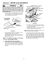
FIGURE 4.17 


5.  Hold the slotted end of the drive disc bolt with a 
screwdriver and remove the nut and internal tooth lock 
washer.  See Figure 4.17. 
6.  Lift the drive disc off the idler arm and remove worn 
belt. 
7.  Loop one end of new belt over engine pulley and 
insert the other end through slot in deck. See Figure 
4.17. 
8.  Loop the belt around the pulley on the bottom of the 
drive disc. 
9.  Reinstall drive disc and retaining hardware. 
10.  Reinstall blade hub and cutter blade. Recom-
mended torque for blade cap screw is 30 to 40 ft. lbs. 
11.  Use a stiff wire, such as a coat hanger, with a hook 
fashioned on one end to pull the hooked end of the idler 
spring through the large hole in the right wheel bracket. 
See Figure 4.18. 
12.  Reinstall the driven disc assembly. 


FIGURE 4.18 


4.4.2.  Transmission Poly-V Belt Replacement 
1.
 Remove the driven disc. Refer to Section 
“Replacing Driven Disc Rubber Ring” for procedure. 
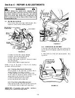
2.  Note the routing of the old belt around the three 
pulleys before removing it.  See Figure 4.19. 
3.  Place new Poly-V Belt over end of hex shaft and 
onto driven pulley. 
4.  Work belt onto top of idler pulley. 
5. Twist belt sideways and pull it upward between 
the differential bracket and drive pulley and then 
down into the pulley groove.  Make sure the Poly-V 
Belt is above belt guide.  See Figure 4.19. 


FIGURE 4.19 


DRIVE 
DISC 

SLOT IN END 
OF DRIVE 
DISC BOLT 

BUSHING 

IDLER 
ARM 

DECK BRACKET 
(PARTIALLY 
SHOWN) 

IDLER 
SPRING 

NUT 

INTERNAL TOOTH 
LOCKWASHER 

BOLT 
RETAINER 

POSITION 
SCRAPER TO 
CLEAR “V” OF 
PULLEY 

RIGHT 
WHEEL 
BRACKET 

PULL SPRING 
THROUGH LARGE 
HOLE & HOOK 
INTO SMALL HOLE 

IDLER 
SPRING 

DRIVE 
PULLEY 

IDLER 
PULLEY 

POLY-V 
BELT 

DIFFERENTIAL 
BRACKET 

BELT 
GUIDE 

HEX 
SHAFT 

DRIVEN 
PULLEY 

ROUTING OF POLY-V BELT 

Summary of Contents for FRP216012E

Page 1: ...elf Propelled Mower 21 21 Cutting Width 60 6 0 HP Engine Horse Power 12 Series Designation E Electric Start Thank you for buying a SNAPPER Product Before operating your Walk Behind read this manual ca...

Page 2: ...extreme CAUTION when changing directions on slopes DO NOT mow steep slopes or other areas where stability or traction is in doubt 3 Use extra care with crass catchers or other attachments these affect...

Page 3: ...rate engine in enclosed areas Engine exhaust gases contain carbon monoxide a deadly poison MAINTENANCE AND STORAGE 1 DO NOT store mower or fuel container inside where fumes may reach an open flame spa...

Page 4: ...gine Drive Belt 11 Check Transmission Poly V Belt 11 Service Annually 11 Engine 11 Air Filter 11 Engine Oil 11 Storage Procedure 11 SECTION 4 ADJUSTMENTS AND REPAIR 12 20 Mower Blade Replacement 12 Bl...

Page 5: ...the mower become thoroughly familiar with the controls parts and operation of the mower before operating Specific details involving the engine are found in the separate engine owner s manual Study th...

Page 6: ...f spilled fuel dirt grass oil etc Keep engine air intake screen and cooling fins clear at all times 2 2 STARTING OPERATION 2 2 1 ENGINE BLADE Primer Models Electric Start When the ignition key Electri...

Page 7: ...mower forward Forward speed can be adjusted while the mower is moving by changing position of the ground speed control See Figure 2 5 FIGURE 2 5 2 3 STOPPING 1 Stop engine and blade by releasing the...

Page 8: ...F prefix in model number Example FRP216012 The front of the cutting deck on these models has been cut out This allows the blade to have more direct contact with the grass and allows more air flow into...

Page 9: ...cher by sliding connector over flange of adapter See Figure 2 10 Attach grass bag hooks over middle handle cross bar See Figure 2 11 FIGURE 2 10 FIGURE 2 11 WARNING DO NOT operate without entire Grass...

Page 10: ...HOT Avoid serious burns allow sufficient time for all components to cool 1 Refer to Engine Manual for proper oil specifications and procedures 2 For simplest cleanest oil change loosen lower handle w...

Page 11: ...ore operating mower 3 2 5 CHECK TRANSMISSION POLY V BELT 1 Visually check poly v belt for cracking fraying severed or belt strands exposed If worn or damaged replace belt before operating mower FIGURE...

Page 12: ...ip See Figure 4 1 Replace with new blade WARNING DO NOT use a cutting blade that shows signs of excessive wear or damage Refer to Section MOWER BLADE REPLACEMENT for proper blade inspection and servic...

Page 13: ...earance between the inside of the spring hook and the inside of the clutch cable eye with the wheel drive control released See Figure 4 5 FIGURE 4 5 2 To adjust unhook upper spring from cable eye and...

Page 14: ...If oil or grease on the drive disc or driven disc is causing slippage clean discs as follows 1 Wipe away any oil or grease with a clean cloth 2 Use either an approved grease solvent or hot soapy water...

Page 15: ...etighten the connector hex nut securely See Figure 4 10 Move ground speed control to the first speed position then back to the sixth speed position Recheck the 1 8 measurement described previously Rei...

Page 16: ...ws and plate which secure the rubber ring to the driven disc hub See Figure 4 13 4 Install new rubber ring 5 Reverse above procedures for reassembly and installation FIGURE 4 12 FIGURE 4 13 4 3 5 Repl...

Page 17: ...ges the transmission that powers the rear wheels Should these belts become worn they could cause slippage which would impair mower performance The condition of the engine belt and poly v belt should b...

Page 18: ...at hanger with a hook fashioned on one end to pull the hooked end of the idler spring through the large hole in the right wheel bracket See Figure 4 18 12 Reinstall the driven disc assembly FIGURE 4 1...

Page 19: ...contact with electrolyte acid Battery acid is corrosive Rinse empty acid containers with water and mutilate before discarding If acid is spilled on battery bench or clothing etc Flush with clear water...

Page 20: ...meter Five Ball Hydrometer 100 Charged w Sulfate Stop 1 280 12 80v Five Balls Floating 100 Charged 1 265 12 60v Four Balls Floating 75 Charged 1 210 12 40v Three Balls Floating 50 Charged 1 160 12 10v...

Page 21: ...mower blade 1 Service mower blade 2 Loose blade components 2 Service and tighten loose parts 3 Loose or missing air lift if equipped 3 Replace air lifts Tighten to proper torque 4 Lumpy or frayed belt...

Page 22: ...Disc Check for Wear Damage Replacement Page 13 16 X Battery Check Electrolyte Pages 19 X X Charge Battery Pages 19 X Testing Battery Pages 19 20 X Change oil every 25 hours when operating under heavy...

Page 23: ...ginal purchase date SNAPPER will not be responsible for any installation cost incurred The battery warranty only covers original equipment batteries and does not cover damage to the battery or machine...

Page 24: ...24 PRIMARY MAINTENANCE...

Page 25: ...25 PRIMARY MAINTENANCE...

Page 26: ...26 PRIMARY MAINTENANCE...

Page 27: ...27 PRIMARY MAINTENANCE...

Page 28: ...erstand and Follow all warnings and instructions in this manual the engine manual and on the machine engine and attachments If you have any questions about your Snapper product contact your local auth...

Reviews: