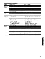
background image

21

Maintenance

Mower Drive Belt Adjustment
(For 28” & 30” Decks Only)

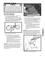
1. Remove the mower drive belt cover.  Refer to the sec-

tion entitled “CHECK MOWER DRIVE BELT”.

2. Move the blade lever up and over to the “ON” position.
3. Place the deck cutting height lever in the third position

(middle notch). Measure the belt spacing 

(B, Figure 36)

between the idler pulley 

(A)

and belt. The distance

should measure 1-1/4” but no less than 1”.

4. If the distance is less than 1”, adjust belt tension:

Move the blade lever to the “OFF” position.
Loosen the hardware 

(A, Figure 37)

that secures 

the clamp that anchors the front frame assembly 

(B)

to the rear main case.

Pull the front frame forward until the belt spacing, 
with the blade lever “ON”, measures 1-1/4”.
Retighten the hardware that secures the clamp. 
Make sure the hardware is tightened securely.

IMPORTANT: 

The SNAPPER Rear Engine Rider Models with

33” decks do not require belt tension adjustment. But, if the
front frame assembly clamp is loosened for any reason,
recheck the belt spacing between the idler pulley and belt.
With the blade lever in the “ON” position, the distance
should measure 1-3/4”.

5. When belt adjustment is complete, it will be necessary

to check Clutch/Brake Cable slack. Disengage the park-
ing brake and allow the pedal 

(A, Figure 38)

to remain

in the engaged wheel drive (Up) position.  The
clutch/brake cable should have approximately 3/16” of
slack. If the cable does not have slack adjustment of
cable must be performed:

Peel back the rubber clutch/brake pedal pad and 
push one ferrule 

(B)

through the hole 

(C) 

in the 

pedal to attain slack in the cable.  
Recheck the cable for the approximate 3/16” of 
slack. Replace the pedal pad when adjustment is 
complete.

IMPORTANT:

Too much slack may cause improper clutching,

and braking could be affected. Too little slack may cause
improper clutch function. Recheck the service brake/park
brake and readjust if necessary. Refer to the section entitled
“SERVICE BRAKE/PARK BRAKE ADJUSTMENT”.

Maintenance (Continued)

WARNING

DO NOT attempt any adjustments, maintenance, service or
repairs with the engine running. STOP engine. STOP blade.
Engage parking brake. Remove key. Remove spark plug
wire from spark plug and secure away from plug. Engine
and components are HOT. Avoid serious burns, allow all
parts to cool before working on machine. Fuel Filler Cap
and vent must be closed securely to prevent fuel spillage.

!

!

Figure 38: Clutch/brake cable adjustment 

C

A

Figure 37: Mower belt adjustment

A

B

Figure 36: Measuring the belt spacing 

A

B

B

Summary of Contents for 2811523BV (7084940)

Page 1: ...rating limitations and environmental factors Please refer to Engine Power Rating Information for further details Manual No 7102295 I R 2 18 2008 TP 100 5350 IR RE N REAR ENGINE RIDING MOWER SERIES 23 Models 2811523BV 7800102 2812523BVE 7800104 3011523BV 7800103 3012523BVE 7800105 3317523BVE 7800254 C2811523BV 7800363 C2812523BVE 7800365 C3011523BV 7800364 C3012523BVE 7800366 C3317523BVE 7800368 ...

Page 2: ..._______________ Retailer_________________________________________________________________________ Retailer s Phone Number___________________________________________________________ Equipment Model Number______________________________________________________________ Serial Number ______________________________________________________________ Engine Model_________________________Type________________...

Page 3: ...wo Years 18 Storage 18 Removing the Fuel Tank 18 Engine Adjustments and Repairs 19 Mower Deck and Component Adjustments 19 Rear Engine Rider Drive Components 22 Mower Blade Replacement 23 Mower Drive Belt Replacement 24 Battery 25 Snapper Rear Engine Rider Accessories 27 Service Schedule 28 Maintenance Replacement Parts 29 Troubleshooting 30 Warranty 32 WARNING Battery posts terminals and related ...

Page 4: ...rcise EXTREME CAUTION on slopes above 10 degrees 18 grade Turn blades OFF when traveling uphill Use a slow speed and avoid sudden or sharp turns 3 DO NOT operate machine back and forth across face of slopes Operate up and down Practice on slopes with blades off 4 AVOID starting stopping or turning on slopes If machine stops going uphill or tires lose traction turn blades OFF and back slowly straig...

Page 5: ...ck open device 10 If fuel is spilled on clothing change clothing immediate ly 11 Never overfill a fuel tank Replace fuel cap and tighten securely Operation 1 Mount and dismount machine from left side Keep clear of discharge opening at all times 2 Start engine from operator s seat if possible Make sure blades are OFF and parking brake is set 3 DO NOT leave machine with engine running STOP engine ST...

Page 6: ... properly tight Check that all cotter pins are in proper position Maintenance Continued From Previous Column 6 Always provide adequate ventilation when running engine Exhaust gases contain carbon monoxide an odor less and deadly poison 7 Disconnect negative black cable from battery before performing maintenance or service Cranking engine could cause injury 8 DO NOT work under machine without safet...

Page 7: ... model Contact your Snapper dealer if you have questions Features and Controls A Steering Wheel B Engine Speed Control hidden from view C Ignition Switch D Clutch Brake Pedal E Park Brake Latch F Blade Pedal G Blade Lever H Discharge Deflector I Override Control J Transmission Shift Lever K Fuel Tank F B H I K D G E J A C Features and Controls ...

Page 8: ...he Reverse Lockout Mechanism With the blade pedals depressed the shift lever must not go into reverse 7 Clean the exterior surfaces of the cutting deck and engine of any accumulation of dirt grass oil etc Keep the engine air intake screen and cooling fins clear at all times 8 Add fuel to the fuel tank after pushing the Rear Engine Rider outside where fumes can dissipate Make sure the fuel filler c...

Page 9: ...he OFF position 3 Press the Clutch Brake Pedal A Figure 5 all the way down and hold while starting the engine 5 Move the engine speed control A Figure 6 to the choke position B to start a cold engine 6 Turn the ignition key A Figure 7 to the START position until the engine starts NOTE If after 5 seconds of cranking the engine does not start release the key make sure the Clutch Brake Pedal is fully...

Page 10: ...filler cap can cause the engine to stall 2 Move the transmission shift lever to the N Neutral position Refer to the section entitled Wheel Drive IMPORTANT DO NOT start the engine with the transmission shift lever in a drive position 3 Make certain the Blade Lever A Figure 4 is in the OFF position 4 Press the Clutch Brake Pedal A Figure 8 all the way down move the park brake latch B over and releas...

Page 11: ... best cutting results move the transmission shift lever into a slow forward speed and the engine speed control to a fast position This combination will allow the mower blades to lift the grass while cutting smoothly and evenly Figure 10 Engaging the mower blade A Operation Continued Figure 11 Engaging the clutch brake pedal A Figure 12 Transmission shift lever A WARNING Once blade is disengaged it...

Page 12: ...ING DO NOT leave the machine with the engine running STOP Blade STOP engine Shift to neutral and engage park brake Remove key WARNING Once blade is disengaged it should come to a complete stop in 3 seconds or less If the blade continues to rotate after 3 seconds the blade brake must be adjusted Refer to Section BLADE BRAKE ADJUSTMENT for adjustment pro cedures or return machine to an authorized SN...

Page 13: ...aged 2 Release the park brake by pressing down firmly on the clutch brake pedal A Figure 17 The park brake latch B is spring loaded and will slide back to the disen gaged position unassisted Cutting Height Adjustment 1 Adjust the cutting height by raising or lowering the deck lift lever A Figure 18 into the desired height of cut notch B Operation Continued WARNING DO NOT park the machine on slopes...

Page 14: ... provided This lever can be pushed and held before starting the blade and will allow reverse operation until the blade pedals are released at which time the system will return to its Reverse Lockout mode This feature should never be selected unless you are absolutely sure that no chil dren or others are present in the mowing area and that all children are away and supervised by a responsible adult...

Page 15: ...new oil Refer to the engine manual for oil specifications 7 Change the oil filter on engines equipped with oil filters at every oil change Refer to the engine manual for serv ice instructions Service Engine Air Cleaner The engine is equipped with a dual element air cleaner Both the foam pre cleaner and cartridge require service Refer to the Engine Manual for recommended service procedures Check Mo...

Page 16: ...continues to rotate longer than 3 seconds do not operate the machine Refer to the section entitled BLADE BRAKE ADJUSTMENT or contact your SNAPPER dealer for assistance Service Brake Park Brake 1 Check the machine brake for proper function Engage the park brake and push the machine The rear tires should skid Drive the machine forward and apply the brake The machine should come to a complete stop in...

Page 17: ...Shift Lever Refer to the section entitled SHIFT LEVER LUBRICATION Service Every 25 Operating Hours Perform all service required after the first 5 hours of opera tion Refer to the section entitled SERVICE AFTER 5 HOURS Check Engine 1 Change the engine oil Refer to the section entitled CHANGE ENGINE OIL Refer to the engine manual for oil specifications 2 Change the air filter Pull up and rotate the ...

Page 18: ...ed FUEL TANK REMOVAL If 3 4 or less proceed to the next step 3 Carefully stand the Rear Engine Rider on the rear bumper 4 Lubricate the spindle grease fitting A Figure 24 with three shots of general purpose grease from a grease gun IMPORTANT If the Rear Engine Rider will be on its rear bumper for longer than two hours remove the battery Refer to the section entitled BATTERY REMOVAL Mower Deck Link...

Page 19: ...needed IMPORTANT Overfilling of the differential with lubricant will cause lubricant to leak onto drive components of the Rear Engine Rider 3 Check the fill level plug A Figure 29 on the chain case B for damage If signs of wear or cracks are visible replace with a new plug 4 To check lubricant in the chain case remove the fill level plug and look for lubricant on the internal components of the cha...

Page 20: ... insure the Rear Engine Rider will operate properly when taken out of storage 1 Thoroughly clean the Rear Engine Rider by removing all grass clippings and debris 2 Perform maintenance and lubrication as required 3 Drain the fuel from the fuel tank 4 Start the engine and allow it to run until the engine runs out of fuel This allows the carburetor and fuel system to remain clean during storage 5 Rem...

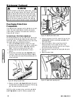
Page 21: ... BELT COVER REMOVAL 3 If the dimension is greater than 3 1 4 rotate the brake adjustment nut A Figure 33 clockwise to increase brake tension If the dimension is less than 3 rotate the nut counter clockwise to decrease brake tension 4 Reinstall the belt cover and tighten the bolts securely Maintenance Continued WARNING DO NOT attempt any adjustments maintenance service or repairs with the engine ru...

Page 22: ...face rotate the blade until the blade tips are at the front and rear of the deck Measure the distance from the blade tips to the floor Figure 35 The distance should be the same or the rear 1 8 to 1 4 lower than the front If the rear blade tip is higher than the front or is more than 1 4 lower than the front proceed with adjustment 30 Decks With the Rear Engine Rider on a smooth level surface rotat...

Page 23: ...ete it will be necessary to check Clutch Brake Cable slack Disengage the park ing brake and allow the pedal A Figure 38 to remain in the engaged wheel drive Up position The clutch brake cable should have approximately 3 16 of slack If the cable does not have slack adjustment of cable must be performed Peel back the rubber clutch brake pedal pad and push one ferrule B through the hole C in the peda...

Page 24: ...stance A Figure 40 between the end of the clutch brake cable B and the bottom of the housing C The measurement should be 3 4 NOTE The cotter pin brake spring and clutch yoke D E and F Figure 40 are noted for reference purposes only 6 If the measurement is not 3 4 loosen the two jam nuts A Figure 41 Hold the clutch brake cable B to the chain case bracket 7 Adjust the cable up or down using the jam ...

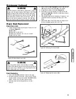
Page 25: ...g cutting edge A 7 Check blade balance after sharpening If necessary cor rect blade balance by grinding the heavy end of the blade 8 Reinstall the blade Torque the blade mounting bolts to the recommended range of 30 to 40 ft lbs Maintenance Continued WARNING DO NOT attempt any adjustments maintenance service or repairs with the engine running STOP engine STOP blade Engage parking brake Remove key ...

Page 26: ...rive disc and into the drive pulley belt groove 8 Remove the idler A Figures 46 and 47 9 Route the belt onto the spindle pulley C Make sure the belt is inside the spindle belt guide D and the idler belt guide B Route the belt as shown 10 Reinstall the idler removed in Step 8 The idler belt guide tab should be positioned in the hole located on the idler arm Tighten the idler pulley bolt securely 11...

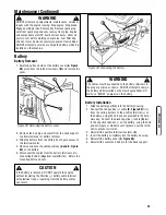
Page 27: ... the positive terminal insulator C 4 Insert the battery completely into the battery housing 5 Reinstall the battery cover A Figure 48 6 Reinstall the swivel and hair pin for the deck support Maintenance Continued WARNING DO NOT attempt any adjustments maintenance service or repairs with the engine running Stop engine Stop blade Engage parking brake Remove key Remove spark plug wire from spark plug...

Page 28: ...e battery using the bolt and nut provided in the hard ware bag Connect the black negative cable A last to the negative terminal on the battery using the bolt and nut Apply a small amount of grease over the termi nals to prevent corrosion 11 Insert the battery completely into the battery housing 12 Reinstall the battery cover A Figure 48 13 Reinstall the swivel and hair pin for the deck support Bat...

Page 29: ...Bag N Wagon All 28 33 Deck Rear Engine Riders 7060948 Thatcherizer All Series 7 Newer Riders 7060964 Wagon Cover All 28 33 Deck Rear Engine Riders 7061190 Weight Front All Series 7 Newer Riders 7060959 Dozer Blade 36 Blade All Rear Engine Riders 7060357 Tire Chains Tires 16 x 6 50 8 All Rear Engine Riders 7060358 Tire Chains Tires 16 x 4 80 8 All Rear Engine Riders 7061823 Ninja Recycling Cover Al...

Page 30: ...eck Pressures Page 6 X Drive Belts Check for Wear and Tension Pages 14 24 X X Mower Blades Check for wear Damage Replacement Page 23 X Mower Deck Clean Debris Accumulation Page 6 X X X Lubrication Points Grease or Oil Pages 15 17 X X Lubricate Chain Case and Transmission Check Grease Level Page 17 X X Blade Brake Stopping Time Check Blade Stopping for Proper Operation Pages 14 19 X X Clutch Brake ...

Page 31: ...ter Blade Standard Not Air Lift Compatible N A 30 Cutter Blade Standard Air Lift Compatible 7018069 30 Cutter Blade Ninja Quad Edge 7026565 33 Cutter Blade Standard Not Air Lift Compatible 7034168 33 Cutter Blade Standard Air Lift Compatible 7019523 33 Cutter Blade Mulching 7016982 33 Cutter Blade Ninja Quad Edge 7024741 Air Lift Kit 28 and 33 Decks 7060480 Air Lift Kit 30 Deck 7060735 Engine to C...

Page 32: ...SNAPPER dealer 12 Starter cable loose broken or disconnected 12 Connect starter cable If broken replace with new starter cable 13 Electrical wiring harness disconnected or broken 13 Connect or replace with new wiring harness Engine Stalls After Running 1 Operator not in seat 1 Sit in operator s seat 2 Choke control in the CHOKE position 2 Move choke control to OFF position 3 Fuel tank empty 3 Fill...

Page 33: ...gh 2 Adjust cutting height 3 Engine speed too slow 3 Move throttle control to FAST position 4 Forward speed too fast 4 Move transmission shift lever to a slower speed 5 Terraced cut side to side 5 Adjust side to side level 6 Excessive deck pitch front to rear 6 Adjust front to rear pitch 7 Cutting blade s dull or damaged 7 Sharpen cutting edges or replace blade s 8 Mower belt slipping 8 Adjust ten...

Page 34: ...r from the original purchase date SNAPPER will not be responsible for any installation cost incurred The battery warranty only covers original equipment batteries and does not cover damage to the battery or machine caused by neglect or abuse destruction by fire explosion freezing overcharging improper maintenance or use of improper electrolyte There is no other express warranty DISCLAIMER OF WARRA...

Page 35: ...33 Slope Guide ...

Page 36: ...www snapper com 34 Notes ...

Page 37: ...35 Notes ...

Page 38: ...www snapper com 36 Notes ...

Page 39: ...37 Notes ...

Page 40: ...ncluding but not limited to accessories air cleaner exhaust charging cooling carburetor fuel pump etc application limitations ambient operating conditions temperature humidity altitude and engine to engine variability Due to manufacturing and capacity limitations Briggs Stratton may substitute an engine of higher rated power for this Series engine Common Service Parts Part Number Cutter Blade 28 S...

Reviews: