background image

15

Operation

Figure 2.  Engine Controls
A. Electric Start Button (Select Models)
B. Electric Start Connection (Select Models)
C. Stop Switch
D. Engine Key
E. Starter Handle
F. Primer Button
G. Choke Knob

Operation

STARTING CONTROLS

See Figure 2 for the following instructions.

Electric Start

1. Electric Start Button 

- The Electric Start Button

(A) activates an electric starter mounted to the
engine, eliminating the need to pull the starter
handle. The Electric Start Button operates on AC
current, which is provided by connection (B) to the
extension cord provided with units equipped with
this feature.  

Connect this extension cord ONLY

to a properly grounded 3 prong electrical
outlet.

Manual Start

2. Starter Handle 

- The starter handle (E) connects

to a starter cord to manually start the engine.
Pulling starter handle rapidly spins the engine
crankshaft, cycles the engine, and generates the
spark necessary for starting the engine.

3. Primer Button

- When pressed, the primer button

(F) provides initial fuel to help start a cold engine.
Normally, pressing the primer button twice will
provide enough fuel to start a cold engine.

A

F

G

B

D

E

C

4. Engine Key

- The engine key (D) prevents the

engine from being started by unauthorized
individuals. The key must be fully inserted into the
key slot for the unit to start. The key is also used to
stop the engine by pulling the key out of the key
slot.

5. Choke Knob

- The choke knob (G) adjusts the

air/fuel mixture, and is used to help start a cold
engine by providing a richer mixture. Once the
engine is warm and running smoothly, the choke
knob should be set to the off position to provide a
normal air/fuel mix.

6. Stop Switch 

- Switch (C) to the ON position to

operate the engine.  Switch to the OFF position to
stop the engine.

Summary of Contents for 1695302

Page 1: ... 08 2007 TP 100 4609 01 IW SN CAUTION Read and follow all instructions Intermediate Frame Snowthrowers Mfg No Description 1695302 SMI I924E B S 24 1695311 SMI I924EX B S 24 CE 1695410 SMI I924RX MS B S 24 CE 1695313 SNP I924E B S 24 1695314 SNP I1924EX B S 24 CE 1695411 SNP I924RX MS B S 24 CE ...

Page 2: ...om an industry leader in outdoor power equipment manufacturing Although reading this manual and the safety instructions it contains will provide you with the necessary basic knowledge to operate this equipment safely and effectively we have placed several safety labels on the unit to remind you of this important information while you are operating your unit All DANGER WARNING CAUTION and instructi...

Page 3: ...Selector 17 Engine Speed 17 Deflector 18 Scraper Bar Skid Shoes 18 Traction Drive Lock 18 Clearing a Clogged Discharge Chute 19 After Each Use 19 Storage 19 Maintenance 20 Maintenance Schedule 21 Checking Tire Pressure 21 Auger Gear Case Lubrication 21 Lubrication 21 Regular Maintenance 22 Troubleshooting Adjustment and Service 24 Troubleshooting 24 Adjustments 26 Auger Drive Adjustment 26 Tractio...

Page 4: ...rate your unit as well as DURING operation Safe operating techniques an explanation of the product s features and controls and maintenance information is included to help you get the most out of your equipment investment Be sure to completely read the Safety Rules and Information found on the following pages Also completely read the Operation section Children Tragic accidents can occur with childr...

Page 5: ...nd throw snow and ice Thrown debris could seriously injure a bystander ALWAYS direct the discharge chute away from bystanders and property that could be damaged by frying debris Be sure to clean up the area to be cleared BEFORE you start Do not allow anyone in the area while the unit is running If someone does enter the area shut the unit off immediately until they leave Fuel and Maintenance Gasol...

Page 6: ...ke any adjustments while the engine motor is running except when specifically recommended by the manufacturer 8 Let engine motor and machine adjust to outdoor temperatures before starting to clear snow 9 Always wear safety glasses or eye shields during operation or while performing an adjustment or repair to protect eye from foreign objects that may be thrown from the machine OPERATION 1 Do not pu...

Page 7: ...osure 3 Always refer to the operator s manual for important details if the snowthrower is to be stored for an extended period 4 Maintain or replace safety and instruction labels as necessary 5 Run the machine a few minutes after throwing snow to prevent freeze up of the collector impeller 6 If fuel is spilled do not attempt to start the engine but move the machine away from the area of spillage an...

Page 8: ...putation hazard Contact with moving parts inside chute will cause serious injury Shut off engine before unclogging discharge chute Use clean out tool not hands 1733057 DANGER Part No 1733057 Discharge Chute Danger Decal Part No 728183 Important Over Adjustment V BELTS STRETCH UNDER NORMAL USE WHICH WILL AFFECT DISCHARGE PERFORMANCE AND SHOULD BE PERIODICALLY ADJUSTED REFER TO MANUAL FOR INSTRUCTIO...

Page 9: ... Decal Export CE Part No 1727208 Auger Danger Decal Part No 1727207 Discharge Chute Danger Decal ALL MODEL DECALS CE MODEL DECALS Decals Part No 724172 SMI SNAPPER Speed Control Decal All Models 9 5 4 3 7 1 Part No 728183 Important Over Adjustment ...

Page 10: ... before performing repairs or maintenance WARNING DISMEMBERMENT This machine can amputate limbs Keep bystanders and children away when engine is running DANGER DISMEMBERMENT The auger can amputate limbs Keep hands and feet away from auger and rotating parts DANGER DISMEMBERMENT The impeller can amputate limbs Stop the engine remove the key and disconnect spark plug wire before clearing the dischar...

Page 11: ... xxx S S A A M M P P L L E E S S A A M M P P L L E E North American CE Models CE Models Only ENGINE REFERENCE DATA Model Description Name Number Unit MFG Number PRODUCT REFERENCE DATA Unit SERIAL Number Dealer Name Date Purchased Engine Make Engine Type Spec Engine Model Engine Code Serial Number Mower Deck MFG Number Mower Deck SERIAL Number CE IDENTIFICATION TAG MARKINGS A Manufacturer s Identif...

Page 12: ...lied in specific sequences To learn what combination and sequence of controls to use for various tasks see the OPERATION section Speed Selector Selects forward speeds 1 6 and reverse speeds 1 2 No neutral position or gate is required since the traction drive design automatically provides neutral no forward or reverse movement whenever the Drive Control is released Auger Control Engages the auger i...

Page 13: ...current which is provided by connection of the extension cord provided Connect this extension cord ONLY to a properly grounded 3 prong electrical outlet Recoil Starter All Models Pulling the recoil handle cranks the engine Fuel Fuel tank filler cap see illustration Note The fuel shut off valve is located under the fuel tank or on the front of the engine Close the valve when the snowthrower is not ...

Page 14: ...ain in position when released If the speed selector does not move freely into all forward and reverse speed positions contact your local authorized dealer for assistance WARNING This unit is a two stage snowthrower The first stage is the auger which feeds the snow back into the impeller housing The second stage is the impeller which throws the snow out the discharge chute If bodily contact is made...

Page 15: ...the engine Pulling starter handle rapidly spins the engine crankshaft cycles the engine and generates the spark necessary for starting the engine 3 Primer Button When pressed the primer button F provides initial fuel to help start a cold engine Normally pressing the primer button twice will provide enough fuel to start a cold engine A F G B D E C 4 Engine Key The engine key D prevents the engine f...

Page 16: ... 6 Push the primer button C two times Note Do not use the primer to start a warm engine Figure 4 Safety Key Choke and Primer Button A Safety Key B Choke Control Knob C Primer Button C A B 7 Rewind Start Firmly hold the starter cord handle A Figure 5 Pull the starter cord handle slowly until resistance is felt then pull rapidly Note If the engine does not start after three attempts see the Engine M...

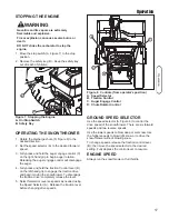
Page 17: ...the auger engage control will disengage the auger 4 Fully press and hold the traction Control lever B on the left hand grip to engage the traction drive and begin moving the snowthrower To disengage the traction drive completely release the lever 5 Select forward or reverse speeds as needed using the Speed Selector A Release the traction lever before changing drive speeds Figure 7 Stopping the Eng...

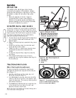
Page 18: ...ise to loosen then adjust the deflector to the desired position and tighten the deflector adjustment knob by turning it clockwise to secure the deflector in position SCRAPER BAR SKID SHOES On smooth surfaces such as concrete or asphalt the scraper bar A Figure 10 should scrape the surface On surfaces such as gravel the scraper bar should be high enough so that it will not pick up gravel or debris ...

Page 19: ...to humans and animals WARNING Never store the unit with gasoline in engine or fuel tank in a heated shelter or in enclosed poorly ventilated enclosures Gasoline fumes may reach an open flame spark or pilot light such as a furnace water heater clothes dryer etc and cause an explosion Handle gasoline carefully It is highly flammable and careless use could result in serious fire damage to your person...

Page 20: ...tem when tires are filled MAINTENANCE SCHEDULE Check Lubricate Hand Linkage Lubricate snowthrower Check tire pressure Change engine oil Clean or replace spark plug Check drive linkage belt tension Lubricate Axle Shafts Check auger gear case lubrication Lubricate Auger Shaft 10 Hours 10 Hours Monthly 50 Hours Yearly 4 6 Hours Yearly 25 Hours 10 Hours 10W Oil 10W Oil and Grease 20 psi 1 37 bar See E...

Page 21: ...symbol Use grease fittings when present Disassemble parts to apply grease to moving parts when grease fittings are not installed Oil locations indicated by oil can symbol Do not allow oil to drip onto traction drive or friction disc IMPORTANT NOTE It is very important that grease fittings on the auger shaft are lubricated regularly If auger rusts to shaft damage to worm gear may occur if shear pin...

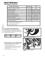
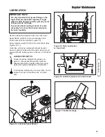
Page 22: ...d shear pin B 2 Use a grease gun and squirt several shots of grease into grease fitting A 3 Rotate auger assembly D several times to distribute the grease evenly Repeat step 2 4 Reinstall shear pin B and cotter pin C 5 Repeat procedure for other side B D IMPORTANT NOTE It is very important that grease fittings on the auger shaft are lubricated regularly If auger rusts to shaft damage to worm gear ...

Page 23: ...23 Maintenance ...

Page 24: ...ealer for adjustments 3 Spark plug faulty fouled or gapped improperly 3 Clean and gap or replace 4 Fuel cap vent is blocked 4 Clear vent Scraper bar does not clean hard surface 1 Skid shoes improperly adjusted 1 RAISE skid shoes this lowers the scraper bar 1 Skid shoes improperly adjusted 1 LOWER skid shoes this raises the scraper bar Auger does not rotate 1 Auger control not engaged 1 Engage auge...

Page 25: ...TER hole 4 Change traction lock pins to INNER hole to engage traction drive 5 Friction disc worn 5 Replace disc see your dealer Snowthrower does not drive and auger does not rotate 1 Belts are wet 1 Clean snow and moisture off of snowthrower and allow belts to dry 2 Traction drive clutch cable loose 2 Tighten to remove slack See adjustment procedure Discharge control is difficult to operate 1 Gear...

Page 26: ...e cables are not over tightened With speed selector in position 1 and traction drive control fully released push snowthrower forward The unit should move forward freely If unit does not move forward freely the cable has been over tightened To remedy loosen tension on clutch cable slightly and recheck WARNING Do not over tighten as this may lift the lever and cause auger drive to be engaged without...

Page 27: ...e the position of the friction wheel A Figure 24 The correct distance from the right side of the friction wheel to the outside of the frame is 4 5 16 10 95 cm If the friction wheel is not in the correct position adjust as follows 9 Move the friction wheel A Figure 24 to the correct distance 4 5 16 10 95 cm 10 Tighten the 1 4 20 shift lever nuts B Figure 23 to 60 lb in 6 8 Nm 11 Check that the snow...

Page 28: ... B and move auger idler pulley towards belt about 1 8 inch 3mm 4 Tighten nut D 5 Engage auger drive clutch Check tension on belt opposite idler pulley Belt should deflect about 1 2 inch 12 5 mm with moderate pressure see Figure 26 You may have to move the idler pulley more than once to obtain the correct tension 6 Reinstall belt cover A Figure 25 securing with screws B 7 Whenever belts are adjuste...

Page 29: ...f bolts screws or a harder shear pin will lead to damaged equipment WARNING Do not go near the discharge chute or auger when the engine is running Do not run the engine with any cover or guard removed Figure 28 Belt Guide A Idler Pulley Engaged Position B Belt Guide C Capscrew D Belt A 1 8 3 18mm C B BELT GUIDE ADJUSTMENT 1 Disconnect spark plug wire 2 Remove screws B Figure 25 from belt cover A R...

Page 30: ... Traction Drive Spring F Traction Drive Pulley Engine G Traction Drive Pulley H Impeller Pulley I Swing Plate Axle Rod J E Ring K Auger Idler Pulley L Traction Drive Idler Pulley Figure 28 Bottom Cover A Capscrews B Bottom Panel C Auger Housing C Service 4 Loosen screw B Figure 24 from belt cover A Remove belt cover A 5 Loosen the belt guide B Figure 29 Pull the belt guide away from the auger driv...

Page 31: ... 2 carriage bolts B securing the offset tube C to the tube support bracket D Figure 32 Offset Tube Lower Removal A Nuts KEPS hex 5 16 18 B Bolts Carriage 5 16 x 1 1 2 C Tube Offset D Bracket tube support D B A 12 Remove the upper four capscrews A Figure 34 that hold together the auger housing C and the frame D Loosen the lower two capscrews B The auger housing C and the frame D can now be split ap...

Page 32: ...he traction drive belt is worn or damaged replace the belt as follows 1 Disconnect the spark plug wire 2 Remove the auger drive belt See Belt Replacement in the Service section 3 Remove the traction drive spring E Figure 29 4 Remove the e ring J Figure 29 from one end of the swing plate axle rod I 5 Remove the swing plate axle rod I to allow the swing plate A Figure 35 to pivot forward 6 Remove th...

Page 33: ...33 Adjustments Service Service Figure 35 Traction Belt Change A Swing Plate B Alignment Tabs A B ...

Page 34: ...34 Adjustments Service Service NOTES ...

Page 35: ...ot develop the rated gross power when used in a given piece of power equipment actual on site or net power This difference is due to a variety of factors including but not limited to accessories air cleaner exhaust charging cooling carburetor fuel pump etc application limitations ambient operating conditions temperature humidity altitude and engine to engine variability Due to manufacturing and ca...

Page 36: ...36 Specifications ...

Page 37: ...d torque values are also included For applicable manuals currently available for your model contact our Customer Publications Department at 1 877 249 6647 and have the information listed in the box below available when phoning in your request Technical manuals can be downloaded from www simplicitymfg com www snapper com Engine Oil Touch Up Paint Grease Gun Kit 8 oz Grease Tube Tire Sealant Degrime...

Page 38: ...Box 997 Port Washington WI 53074 0997 www SimplicityMfg com Briggs Stratton Yard Power Products Group Copyright 2007 Briggs Stratton Corporation Milwaukee WI USA All Rights Reserved PRODUCTS 535 Macon Street McDonough GA 30253 www Snapper com ...

Reviews: