Models
42010 - 8 HP, 24" Auger42030 - 8 HP, 24" Auger42012 - 10 HP, 26" Auger42031 - 10 HP, 26" Auger
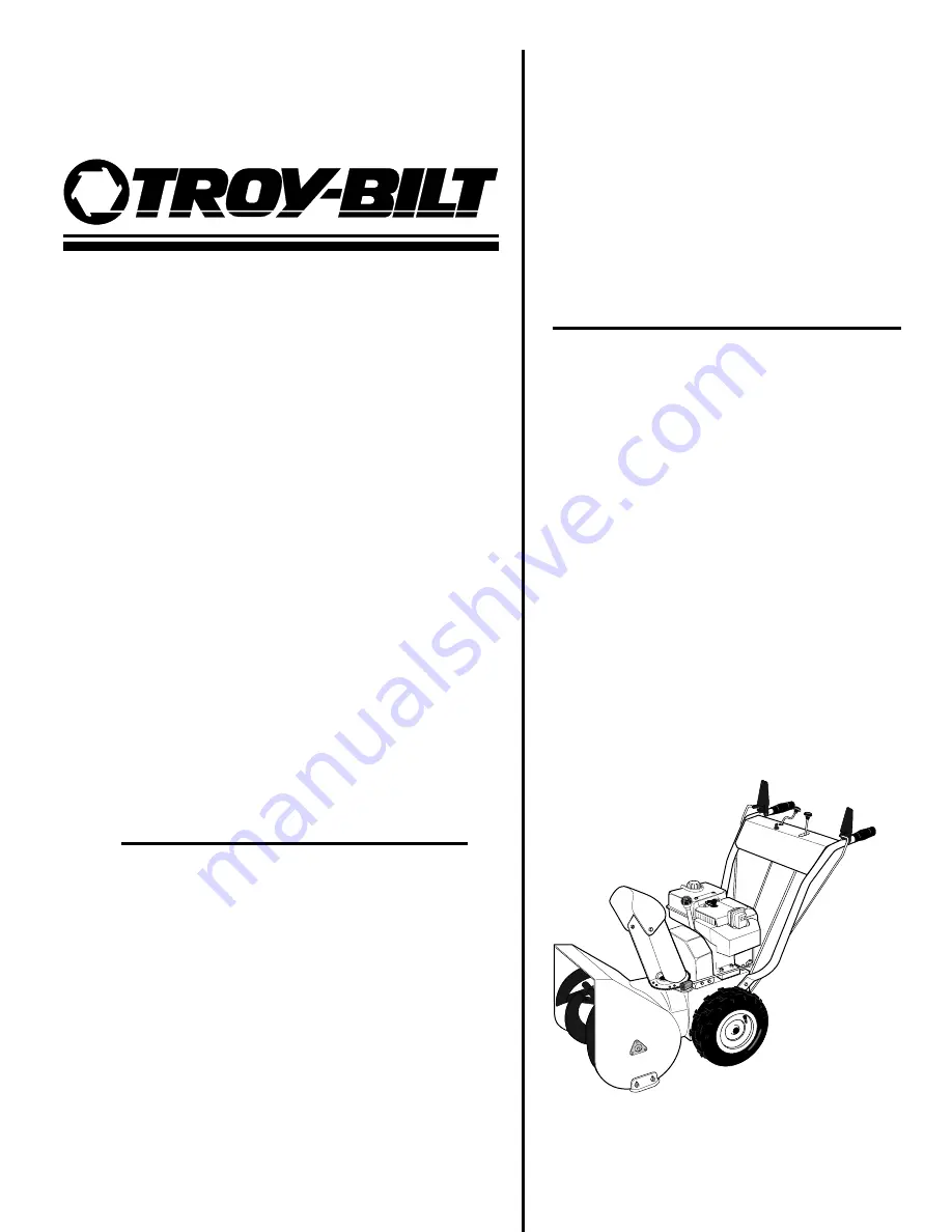
Owner/OperatorManual
Snowthrower
• Safety• Assembly• Controls• Operation• Maintenance
®
GARDEN WAY INCORPORATED
Page 1: ...Models 42010 8 HP 24 Auger 42030 8 HP 24 Auger 42012 10 HP 26 Auger 42031 10 HP 26 Auger Owner Operator Manual Snowthrower Safety Assembly Controls Operation Maintenance GARDEN WAY INCORPORATED ...
Page 2: ... telephone numbers and mailing address are listed on page 3 and on the back of this manual We want to ensure your complete satisfaction at all times Safety Alert Symbol This is a safety alert symbol It is used in this manual and on the unit to alert you to potential hazards When you see this symbol read and obey the message that follows it Failure to obey safety messages could result in personal i...
Page 3: ...Blade 26 Off Season Storage 26 Troubleshooting Chart 27 Maintenance Schedule 29 Specifications 30 Wiring Diagram 31 Customer Service and Technical Service If you have questions or problems with the unit contact your authorized dealer or call or write the factory When calling or writing the factory provide the model serial numbers of the unit Replacement Parts Factory specified replacement parts ar...
Page 4: ... Preparation 1 Wear approved safety glasses or eye shields and hearing protection when operating the unit The operation of any powered machine can result in foreign objects being thrown by high speed rotating parts 2 Do not wear loose fitting clothing such as scarves which could be caught by moving parts Tie up or restrain long hair Safety 4 SPARK ARRESTER WARNING TO RESIDENTS OF CALIFORNIA AND SE...
Page 5: ...ands or wet gloves Do not use the electric starter if it is raining e Connect the cord to the electric starter first and then plug the cord into a properly grounded outlet this lessens the chances of sparks from occurring near the engine f Do not abuse the electrical cord Do not pull the unit by the cord Do not pull the cord to disconnect it from the outlet Keep the cord away from sharp edges oil ...
Page 6: ...tory customer service department at the address and phone number on page 3 if you are not sure about the use of any attachment or accessory 25 Operate the unit only in daylight or in good artificial light 26 Do not tamper with the engine governor settings The governor controls the maximum safe engine operating speed and protects the engine and moving parts from damage Contact your local engine dea...
Page 7: ...ove the ignition key from the ignition keyswitch 10 Check the tightness of the auger shear bolts and other fasteners at frequent intervals Torque shear bolts to 11 ft lbs 15 Nm 11 Maintain or replace safety and instruction decals as needed if they are damaged or illegible Refer to the parts catalog for decal location and ordering information 12 Refer to the engine owner manual for complete engine ...
Page 8: ...are Bag Contents The hardware bag should contain the items listed below and shown in Fig 2 2 These items are extra auger shear bolts and locknuts if the auger catches a hard obstruction the shear bolts are designed to break to prevent damage to the auger and other parts See the Maintenance section for replacement steps C Unpacking Instructions The shipping crate should contain Snowthrower engine a...
Page 9: ...ollows use the four 3 8 16 x 3 4 hex flange screws supplied in hardware bag a Install two screws in the upper mounting holes C Fig 2 3 on each side Leave screws loose enough to allow handlebar to pivot b Install two screws D in the lower mounting holes c Using light pressure press down on the left side handlebar and tighten the two screws Repeat on the right side handlebar 3 There are four pre ins...
Page 10: ... centered with the teeth on the flange of the discharge chute base c Reinstall the washer and locknut on the screw M and tighten securely Fig 2 4 d Turn chute control rod F Fig 2 4 by hand to be sure the worm gear and discharge chute rotate freely but with enough resistance to prevent free rotation of the discharge chute during snow removal operation Readjust position of worm gear assembly as nece...
Page 11: ...2 8 while completing the following steps 3 Hold the jam nut AT in place with a 7 16 wrench and use another 7 16 wrench to thread the adjusting thimble AS downward a total of 12 turns 4 Raise auger drive control handle X Fig 2 6 all the way up Then hook the spring AC Fig 2 8 at the lower end of the auger drive control rod AA into the hole in the auger drive control arm AD 5 Thread the adjusting thi...
Page 12: ...adjusted at the factory When the engine is started as described in the Operation section you will be given a functional check to make sure the wheel drive control rod is properly adjusted J Install Gear Shift Control Rod 1 Place the gear shift select lever T Fig 2 6 in the No 5 position 2 Gently push the transmission shift arm AB Fig 2 9 fully downward 3 Align the holes in the transmission shift a...
Page 13: ... the wheel M Check Auger Gear Case Oil Level The auger gear case was filled at the factory with the correct amount of SAE 90 gear oil This level should be checked before using the unit Refer to Lubrication in the Maintenance section of this manual for complete information N Check Tire Pressure Check the air pressure in both tires using an automotive type tire pressure gauge Inflate tires evenly to...
Page 14: ...s facing Rotate this crank clockwise to turn the discharge to the right rotate counter clockwise to turn the discharge chute to the left Approximately ten turns of this crank will move the discharge chute all the way from one side to the other E F Fig 3 2 Discharge chute deflector cap and lever Controls the vertical angle of the snow discharge To adjust the discharge angle move the discharge cap b...
Page 15: ...ration information L Fig 3 4 Choke knob Controls the amount of gasoline in the air gasoline mixture that is fed into the engine This is known as choking the engine It is often necessary to choke a cold engine when starting Refer to the following section Operation for proper operation information M Fig 3 5 Skid shoes Controls the distance between the auger housing scraper blade and the ground This ...
Page 16: ... Wipe the oil from the dipstick with a clean cloth d Screw the dipstick back into the engine e Remove the engine oil dipstick O Fig 4 1 again f The oil level should be between the FULL and the ADD marks on the dipstick Refer to the engine owner manual for proper engine oil specifi cations 5 Remove the gasoline tank fill cap A and check the level of gasoline in the gasoline tank Fig 4 1 A J K Fig 4...
Page 17: ...blade N at the carriage bolts Z Fig 4 2 Adjust the bottom edge of the scraper blade so it is parallel to the bottom edge of the auger 8 Adjust the discharge chute deflector cap AA Fig 4 3 with lever to the desired angle of discharge Usually keep the angle of the discharge defector cap low especially in windy conditions 9 Rotate the discharge chute control rod crank P Fig 4 3 and check for binding ...
Page 18: ... a properly grounded 3 pronged 110V outlet 8 Push the starter button on the switch box When the engine starts release the button NOTE The starter is thermally protected When overheated from continuous use the starter will stop functioning Allow the starter to cool for several minutes before attempting to restart engine 9 Move the choke knob D Fig 4 5 out of the full choke position Turn the choke o...
Page 19: ...ng snow engage only the wheel drive lever Auger drive Wheel drive interlock feature The auger drive wheel drive interlock feature allows the auger and the wheels to be operated with just one hand thus freeing the other hand to operate the chute control crank rod To engage both functions squeeze both the auger and the wheel drive levers all the way down Holding just the wheel drive lever will keep ...
Page 20: ...ds for safety and to prevent overloading the unit Snowthrowing Patterns Use pattern in Fig 4 7 when snow can only be thrown to one side Begin throwing snow closest to the side opposite where it can be thrown and direct the discharge away from that side When turning the unit around after each pass rotate the discharge chute as you proceed so snow continues to be thrown in the proper direction Use p...
Page 21: ...s Fill the engine through the oil dipstick opening with the correct type and amount of oil as indicated in the engine owner manual 10 Securely replace the oil dipstick A NEVER DISPOSE OF WASTE OIL ON THE GROUND DOWN A DRAIN OR INTO A LAKE POND OR STREAM CONTACT LOCAL ENVIRONMENTAL AUTHORITIES FOR PROPER OIL DISPOSAL INSTRUCTIONS Ignition system The engine has an electronic ignition system which do...
Page 22: ...gs O Fig 5 7 using a grease gun Rotate auger three or four times Reinstall shear bolts torque to 11 ft lbs 15Nm 9 Check the auger gear case oil level a Place the unit on a smooth level surface Unscrew the plug P Fig 5 7 from the front of gear case b Inspect plug hole Oil should just begin to seep out of the hole Add SAE 90 gear oil if necessary until oil just begins to flow out of hole Let the exc...
Page 23: ... wheel drive control lever against the handlebar X Fig 5 3 to increase the gap between lower pulleys as needed 6 Remove the belt from unit To install the wheel drive belt 1 Position the belt into lower drive pulley closest to the engine 2 Place the belt into the groove closest to the engine Reinstall the auger drive belt in its pulley 3 Position the belt guide AC back on the engine and secure with...
Page 24: ...nger than the measurement taken in step 4 If it does not loosen the jam nut AM and turn the adjuster AN to increase or decrease the length of the spring Hold the adjuster and tighten the jam nut AM when the correct spring length is obtained Re check the measurements and adjust if needed NOTE 1 1 4 turns of the adjuster equals 1 16 1 5mm of spring extension Auger Drive Belt Replacement To remove th...
Page 25: ...er from the pivot block N Fig 5 14 Disconnect the pivot block N from the gear shift lever plate AV Fig 5 14 2 Pull the gear shift control rod AA Fig 5 10 down completely 3 While holding the gear shift control rod down AA loosen the jam nut ZZ Fig 5 14 and thread the pivot block N up or down as needed so it fits into the hole in the gear shift lever plate AV 4 Reinstall the pivot block into the gea...
Page 26: ...skid shoes M into the proper position 2 The scraper blade N Fig 5 16 can also be adjusted Adjust the scraper blade N at the carriage bolts Adjust the bottom edge of the scraper blade so it is parallel with the bottom edge of the auger Off season storage When storing the unit for more than 90 days follow these procedures to help keep the unit in good condition for future use Clean dirt grime and gr...
Page 27: ...starting position Push primer button several more times Rotate choke knob to OFF position move throttle lever to idle position attempt to start engine then proceed with normal starting procedure DO NOT re prime Connect spark plug wire to spark plug Remove clean inspect re gap or replace spark plug Fill gasoline tank Open fuel shutoff valve Contact dealer Rotate choke knob to correct setting Rotate...
Page 28: ...auger drive belt Skid shoes set too high Scraper blade adjusted incorrectly Skid shoes not set at equal height Scraper blade adjusted incorrectly Electrical cord unplugged from outlet Blown fuse or thrown circuit breaker Faulty electrical cord or plug Overheated starter SOLUTION Replace key Replace key Decrease spring tension Increase spring tension Replace chain s Re adjust drive disc Replace whe...
Page 29: ...te service information contact your local authorized dealer Maintenance Chart Optional Kits and Accessories Kit Description Model Part Number Electric Starter Kit 110V Allows for electric starting of the unit using house current 6857 Electric Starter Kit 12V D C Allows for electric starting of the unit using battery 16008 Tire Chain Kit Includes tire chains for added traction 1756278 Drift Slicer ...
Page 30: ... 42030 3 125 x 2 5312 in 79 9 x 64 31 mm 42012 42031 3 3125 x 2 5312 in 84 14 x 64 31 mm Carburetor Float type primer and choke winterized Governor Mechanical High Speed 3450 RPM Idle Speed 1700 RPM Speed Setting 3450 RPM Lubrication Splash system Oil Fill Extended oil fill and dipstick on top of cylinder Oil Drain Rear Engine Oil Type Refer to engine owner s manual for manufacturer s recommendati...
Page 31: ...FIER ENGINE CONNECTOR RED BLUE IGNITION SWITCH HANDLEBAR HEATER HANDLEBAR HEATER GROUND TO HANDLEBAR BLACK To Light optional BLACK RED RED YELLOW RED YELLOW ENGINE SHROUD GROUND SCREW ENGINE CONNECTOR RED GREEN OFF ON TO MAGNETO TO ENGINE STATOR ...
Page 32: ...2180 Customer Service 1 800 437 8686 Technical Service 1 800 520 5520 Parts Service 1 800 648 6776 FAX 518 391 7332 Outside the U S A and Canada Customer Service 518 391 7007 For Technical Service 518 391 7008 Parts Service 518 391 7006 or FAX 518 391 7332 Form 1774200 Rev B 9 98 Printed in U S A 1998 GARDEN WAY INCORPORATED ...