background image

5

GENERAL DESCRIPTIONS

This welder is a constant current welder built using IN-
VERTER technology, designed to weld with stick elec-
trodes and for TIG procedures, with scratch starting.
IT MUST NOT BE USED TO DEFROST PIPES.

EXPLANATION OF TECHNICAL SPECIFICATIONS 
LISTED ON THE MACHINE PLATE

This welder is manufactured according to the following 
international standards: IEC 60974.1.
N°. 

Serial number, which must be indicated on 
any type of request regarding the welding 
machine. 

  Single-phase static transformer-rectifier    

frequency converter.


Drooping characteristic.

SMAW. 

Suitable for welding with covered elec-
trodes.

TIG 

Suitable for TIG welding.

U0. 

Secondary open-circuit voltage  

X. 

Duty cycle percentage. % of 10 minutes dur-
ing which the welding machine may run at a 
certain current without overheating.

I2. 

Welding current

U2. 

Secondary voltage with current I2

U1. 

Rated supply voltage.


The machine has an automatic supply volt-
age selector.

1~ 50/60Hz  50- or 60-Hz single-phase power supply
I1 max.  

This is the maximum value of the absorbed 
current.

I1 eff.  

This is the maximum value of the actual cur-
rent absorbed, considering the duty cycle.

IP23S 

Protection rating for the housing.


Grade 3 as the second digit means that this 
equipment may be stored, but it is not 


suitable for use outdoors in the rain, unless 


it is protected.

S


Suitable for hazardous environments.

NOTE:
The welder has also been designed for use in environ-
ments with a pollution rating of 3. (See IEC 60664).

PROTECTION DEVICES

Thermal cutout

This equipment is protected by a thermostat. When the 
thermostat is tripped, the welder stops delivering current 
but the fan continues to run. The yellow led (

B

) lights to 

indicate when it is tripped. Do not shut off the welder until 
the led has gone off.
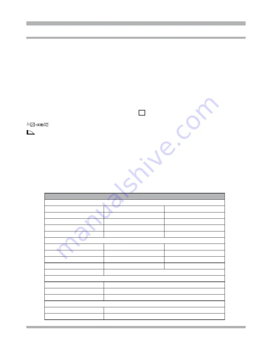
SPECIFICATIONS

SPECIFICATIONS

Power Input

Voltage

115 Volt

230 Volt

Phase

Single Phase

Single Phase

Frequency

50/60 Hertz

50/60 Hertz

Current (MMA stick welding)

30 Amps @ 100 Amps Output

30 Amps @ 130 Amps Output

Current (TIG welding)

15 Amps @ 100 Amps Output

20 Amps @ 130 Amps Output

Power Output

Duty Cycle/Rated Output

100% @ 70 Amps

100% @ 80 Amps

60% @ 80 Amps

60% @ 90 Amps

35% @ 110 Amps

20% @ 130 Amps

Output Control

Adjustable 10 – 110 Amps

Adjustable 10 – 130 Amps

Power Input Cord

8,6 Feet

Dimensions

Height

13,5   Inches

Width

6,75   Inches

Depth

12,75  Inches

Weight

Base Unit

15 lb

Shipping

16,5 lb

Summary of Contents for TIG 130i

Page 1: ...130i This welder TIG 130i is a constant current welder built using INVERTER technology designed to weld with stick electrodes and for TIG procedures with scratch starting Will not TIG weld aluminum INTRODUCTION Form WC 6001 3 300 072 ...

Page 2: ...er Table of Contents 2 Safety Information 3 4 Specifications 5 Features 6 Description of Equipment 7 Assembling the Unit Start up Guide 8 9 Troubleshooting Maintenance 10 Wiring Diagram 11 Replacement Parts 12 13 Warranty Service and Repair 14 ...

Page 3: ...icon when present gives a graphical description of the potential hazard Arc Welding Electric welding or plasma cutting causes ultra violet rays and weld spatter Bystanders will be exposed to ultraviolet rays and weld spatter Wear welding helmet with appropriate shade lens while using electric welders or plasma cutters Do not allow bystanders while welding or cutting Wear safety shield and protecti...

Page 4: ... torch lead around your body Do not work next to welding cutting power source Electrical shock and Magnetic fields can cause injury Disposal of Equipment IMPORTANT Disposal of electrical equipment can be hazard ous to the environment Contact local regulations prior to disposal Improper disposal can cause an environmental hazard FUMES AND GASES can be dangerous to your health ITEMS REQUIRED FOR TIG...

Page 5: ...mum value of the actual cur rent absorbed considering the duty cycle IP23S Protection rating for the housing Grade 3 as the second digit means that this equipment may be stored but it is not suitable for use outdoors in the rain unless it is protected S Suitable for hazardous environments NOTE The welder has also been designed for use in environ ments with a pollution rating of 3 See IEC 60664 PRO...

Page 6: ...will not weld aluminum Inverter technology allows the welder to be lightweight 15lbs and still able to perform most welding applications The adjustable amperage output of a minimum of 10 amps Industry leading technical support of over 30 years of experience by calling 800 ABC WELD to speak with a live expert ...

Page 7: ...7 DESCRIPTION OF EQUIPMENT B A C D F G E H A CURRENT ADJUSTMENT B YELLOW LED SEE PROTECTION DEVICES C POWER ON LED D OUTPUT TERMINAL E OUTPUT TERMINAL F ON OFF SWITCH G MAINS CABLE H TIG TORCH CONNECTOR ...

Page 8: ...and re move the electrode from the clamp after welding TIG WELDING This welding machine is suitable for welding the fol lowing materials using the TIG procedure stainless steel iron copper chrome moly brass nickel Make sure that the switch F is in position 0 Connect the ground cable connector to the positive pole of the welding machine and the clamp to the workpiece as close as possible to the wel...

Page 9: ... Material Polarity Amps THICKNESS Steel Chrome Moly Stainless Steel Cast Iron Brass Nickel Copper DC 25 24 Ga 024 30 22 Ga 030 40 20 Ga 036 50 18 Ga 048 60 16 Ga 060 75 14 Ga 075 105 12 Ga 105 115 11 Ga 115 130 1 8 125 TORCH HEAD ASSEMBLY 1 The electrode to use is the red tipped 2 thorium tungsten 1 16 in diameter 2 Make sure the Teflon heat shield is in place 3 Locate the matching size Collet and...

Page 10: ... source in accordance with applicable electrical codes Do not touch electrode or internal compo nents without protection Disconnect power before servicing Do not remove the grounding lug in any elec trical plug Electrical shock can cause injury In case of maintenance inside the welder make sure the switch F is in O position and that the power supply cable is disconnected from the main Periodically...

Page 11: ...11 WIRING DIAGRAM ...

Page 12: ...12 REPLACEMENT PARTS PARTS LIST 1 3 2 1 9 8 4 5 6 7 10 11 17 18 12 15 14 16 8 13 19 20 21 ...

Page 13: ...008 FRAME 9 CKST13009 POWER CORD 10 CKST13010 CIRCUIT BOARD SUPPORT 11 CKS260453 MOTOR WITH FAN 12 CKST13012 CIRCUIT BOARD COVER 13 CKST13013 POWER CIRCUIT 14 CKST13014 FRONT PANEL 15 CKSP3029 KNOB 16 CKSB7073370 SOCKET 17 CKST13017 BOTTOM 18 CKS3115078 FOOT 19 CKST13019 JUMPER 20 CKST13020 CONNECTION 21 CKST15029 CAP WHEN ORDERING SPARE PARTS PLEASE STATE THE MODEL NUMBER AND SERIAL NUMBER AND PA...

Page 14: ...ent of the Equipment by other than Seller s authorized representatives e installation repair or maintenance other than specified operator maintenance of the Equipment or related equipment attachments peripherals or optional features by other than Seller s authorized re presentatives D improper or negligent use application operation care cleaning storage or handling E fire water wind lightning or o...

Page 15: ...15 ...

Page 16: ...16 ...

Reviews: