3
INSTRUCTION MANUAL FOR WIRE WELDING MACHINES
WARNING!
READ, UNDERSTAND AND FOLLOW THIS MAN-
UAL CAREFULLY BEFORE INSTALLING, USING,
OR SERVICING THE WELDING MACHINE, PAYING SPE-
CIAL ATTENTION TO SAFETY RULES. CONTACT YOUR
DEALER IF YOU DO NOT FULLY UNDERSTAND THESE
INSTRUCTIONS.
1
INSTALLATION
This machine must be used for welding only. It must not
be used to defrost pipes.
It is also essential to pay special attention to the chapter
on SAFETY PRECAUTIONS.The symbols next to certain
paragraphs indicate points requiring extra attention,
practical advice or simple information.
This manual must be stored carefully in a place familiar to
everyone involved in using the machine. It must be con-
sulted whenever doubts arise and be kept for the entire
life-span of the machine; it will also be used for ordering
replacement parts.
1.1
PLACEMENT
Unpack the machine and place it in an adequately venti-
lated area, dust-free if possible, taking care not to block
the air intake and outlet from the cooling slots.
CAUTION!
REDUCED AIR CIRCULATION causes overheat-
ing and could damage internal parts.
Keep at least 20 inches of free space around the machine.
Never place any filtering device over the air intake points
of this welding machine.
The warranty shall become void if any type of filtering
device is used.
2
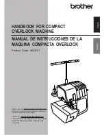
DESCRIPTION OF THE MACHINE
A)
Switch
Turns the machine on and off, and also regulates the
welding voltage range.
B)
Setting knob
This knob serves to adjust the welding wire speed.
C)
Ground cable
D)
Yellow LED
Lights only when the thermostat is tripped and inter-
rupts the machine operation.
E)
Green LED
Indicates that the machine is turned on.
F)
Welding torch
G)
Handle
Use this handle to lift the machine.
3 GENERAL DESCRIPTIONS
3.1 SPECIFICATIONS
This welder is used for welding soft steel, stainless steel
and aluminium.
3.2 EXPLANATION OF TECHNICAL SPECIFICATIONS
N°
Serial number, which must always be indicated
in any inquiry regarding the welding machine.
U
0
Secondary no-load voltage.
X
The duty cycle expresses the percentage of
10 minutes during which the welding machine
can run at a certain current without overheating.
Example: X = 60% at I2 = 100 A
This means that the machine can weld with a
current I2 = 100A for 6 out of 10 minutes, thus
60%.
I
2
Welding current
U
2
Secondary voltage with welding current I2
U
1
Rated power voltage.
1~60Hz
Single-phase 60-Hz power supply.
I
1
Current absorbed at the corresponding welding
current I
2
IP21
Degree of housing protection.
Grade one as the second digit means that this
device is not suitable for use outdoors in the rain.
Fig. 1
C
F
G
D
B
E
A