background image

86

SureTrack Community

SureTrack - Online Community

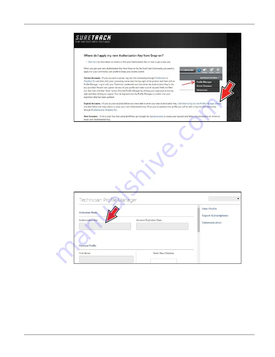
Figure 10-16 

4.

Scroll to the topic “Where do I apply my new Authorization Key from Snap-on?”

5.

Select the link “click here to log into the profile manager login window directly”.

URL - https://profilemanager.mitchell1.com/technicianprofile/index

The SureTrack renewal window opens.

6.

Enter your current username and password.

The SureTrack Profile Manager window opens.

7.

Enter your new 

Authorization code 

(

Figure 10-17

).

Figure 10-17 

8.

Review and update the rest of your profile and make sure all required fields are filled out. 

9.

Select 

Save

10.

Exit the Profile Manager by selecting your username (near the top right) and select 

Logout

11.

When the login screen displays, login using your current username and password.

12.

Confirm the new expiration date by logging back into Profile Manger to check it.

Enter new code here.

Summary of Contents for Ethos-Tech

Page 1: ...User Manual EAZ0075L06D Rev B 30 A 18 NA ...

Page 2: ...p on reserves the right to make changes at any time without notice IMPORTANT Before operating or maintaining this unit please read this manual carefully paying extra attention to the safety warnings and precautions Software License Information Use of Software is governed by the terms and conditions of the End User License Agreement The diagnostic tool should not be initially operated until the End...

Page 3: ...agent Product Training Videos Diagnostic tool specific training videos are available on our website Follow along and learn the basics of diagnostic tool operation with our free training videos Videos are product specific and are available at http diagnostics snapon com Click on the Training Support tab select the applicable diagnostic tool then select See Training NOTE i Sample titles are listed b...

Page 4: ... select See Quick Tips https www youtube com user snaponscanner videos Use the search function to find a title or enter Diagnostic Quick Tips in the search field to see a list of all applicable titles NOTE i URL links above and titles listed below are subject to change and may not be available in all markets A sample list of titles are listed below other titles may be available Some videos may not...

Page 5: ...es Ford Battery Monitor System Oil Specs Service Light Resets Ford Coil Current RFI Test Scope PID Trigger Functions Scanner Ford Flash Reprogramming Piezo Injectors Signature Test Ford Misfire Monitor Neutral Profile Correction Scanner Relative Compression Test Scope Ford PATS Key Programming ShopStream Connect Data Manipulation Ford Relative Compression Test ShopStream Connect Software Updates F...

Page 6: ...Basic Operation and Navigation 12 Turning On Off and Emergency Shutdown 12 Turning On 12 Turning Off 12 Emergency Shutdown 13 Basic Navigation 13 Home Screen Layout 13 Title Bar 14 Home Screen Icons 15 Common Toolbar Control Icons 16 Scroll Bar 17 Screen Messages 18 System Messages 18 Communication Messages 18 Data Cable Connection 19 Chapter 4 Scanner 20 Screen Layout and Toolbar Icons 20 Screen ...

Page 7: ...ostic Tool 66 Cleaning the Touch Screen 66 Battery Service 66 Battery Safety Guidelines 67 Replacing the Battery Pack 67 Disposing of the Batteries 68 Chapter 9 ShopStream Connect 69 Using SSC Connecting to your PC 69 SSC Main Screen 70 Scanner DataViewer 71 Image Viewer 72 Printing the Code Scan Report 73 Software Upgrades and Updates 75 End User License Agreement 76 Chapter 10 SureTrack Communit...

Page 8: ... variations in the products that can be tested with this instrument we cannot possibly anticipate or provide advice or safety messages to cover every situation It is the responsibility of the automotive technician to be knowledgeable of the system being tested It is essential to use proper service methods and test procedures It is important to perform tests in an appropriate and acceptable manner ...

Page 9: ...ate or minor injury to the operator or to bystanders Safety Message Conventions Safety messages are provided to help prevent personal injury and equipment damage Safety messages communicate the hazard hazard avoidance and possible consequences using three different type styles Normal type states the hazard Bold type states how to avoid the hazard Italic type states the possible consequences of not...

Page 10: ... main menu select Continue The Scanner function provides many diagnostic tests The term select describes tapping touching an icon on the touch screen or highlighting an icon or menu choice and then selecting the confirmation menu choice such as Continue Accept OK Yes or other similar choice Abbreviated example for the following procedure Select Brightness 1 Navigate to and highlight the Brightness...

Page 11: ...amage to the test equipment or vehicle Example IMPORTANT Do not disconnect the data cable while the Diagnostic Tool is communicating with the ECM 1 2 5 Hyperlinks Hyperlinks or hot links that take you to other related articles procedures and illustrations are available in electronic documents Blue colored text indicates a selectable hyperlink Example IMPORTANT Read all applicable Safety Informatio...

Page 12: ...specific troubleshooting information This chapter introduces the basic features of the Diagnostic Tool including the control buttons data ports battery pack and power sources Technical Specifications are provided at the end of this chapter 2 1 Control Buttons Figure 2 1 Front view 1 2 3 4 5 Item Button Description 1 N X or Cancel Push type button To exit a menu or program To close an open list and...

Page 13: ...ff Push type button Turns the Diagnostic Tool on and off Also press and hold for 5 seconds for emergency shutdown Item Button Description Item Description 1 DC Power Supply Jack AC power supply connection 2 Battery Status Indicator LED Green battery is fully charged Red battery is charging Amber indicates there is a battery issue correct before operating 3 Mini USB Jack USB cable connection used t...

Page 14: ...s Your Diagnostic Tool can receive power from any of the following sources Internal Battery Pack AC Power Supply Vehicle Power Item Description 1 Built in Stand shown closed The built in stand extends from the back of the Diagnostic Tool and clips into the Diagnostic Tool for storage 2 Battery Cover 2 1 ...

Page 15: ...pply attaches to the DC power supply input jack on top of the Diagnostic Tool Use only the AC power supply provided IMPORTANT Never connect the AC power supply to the DC power supply input on the Diagnostic Tool when the Diagnostic Tool is communicating with a vehicle 2 4 3 Vehicle Power All OBD II EOBD vehicles have vehicle battery power B available on the DLC The Diagnostic Tool is powered throu...

Page 16: ...ime Power Supply Supply Rating 15 VDC 2A DC Operating Voltage 10 to 30VDC Width 11 2 in 285 mm Height 5 98 in 151 8 mm Depth 2 in 50 9 mm Weight including battery 2 6 lb 1 18 kg Operating Temperature Range ambient At 0 to 90 relative humidity non condensing 32 to 113 F 0 to 45 C Storage Temperature ambient At 0 to 70 relative humidity non condensing 4 to 140 F 20 to 60 C Environmental Conditions T...

Page 17: ...he Diagnostic Tool to turn the Diagnostic Tool on 3 1 2 Turning Off IMPORTANT All vehicle communication must be terminated BEFORE turning off the Diagnostic Tool A warning message displays if you attempt to turn the Diagnostic Tool off while communicating with the vehicle Forcing a shut down while communicating may lead to ECM problems on some vehicles Never disconnect the Data Cable when the Diag...

Page 18: ...cedure should only be used If the Diagnostic Tool does not respond to navigation or control buttons or exhibits erratic operation To force an emergency shutdown press and hold the Power button for five seconds until the Diagnostic Tool turns off 3 2 Basic Navigation 3 2 1 Home Screen Layout The Home screen includes a title bar and main body The Home screen contains icons one for each of the primar...

Page 19: ...wered by a dedicated internal battery so the correct time is maintained even when the main battery pack is discharged Use the Tools function to set the clock and format how time is displayed See Clock Settings on page 62 for additional information The Title bar displays other information that varies depending upon what functions are being performed Other information may include The identification ...

Page 20: ...s loaded and ready for use Table 3 2 Home screen icons Function Name Function Icon Description Scanner Used to communicate with the electronic control systems of a vehicle This function allows you to retrieve diagnostic trouble codes DTCs view PID data and perform diagnostic tests See Scanner on page 20 for details OBD II EOBD Allows you to access generic OBD II EOBD data and tests without identif...

Page 21: ...he tools menu Save Writes data from buffer memory to a file The saved movie file can be accessed for future reference by selecting Previous Vehicles and Data View Saved Data The control icons below are used to navigate through paused or saved movie files during playback Step Forward allows forward movement in singular steps To quickly step forward select this icon yellow frame appears then press a...

Page 22: ...yed 2 Step up Moves up one increment of the data displayed 3 Slider position indicator Select and drag the Slider to scroll through data The slider indicates the relative position of the current screen to the total available data 4 Step down Moves down one increment of the data displayed 5 End Moves to end of data displayed The Up b and Down d directional buttons can also be used to move through t...

Page 23: ...unication Software manuals for manufacturer specific problems Message Type Description Loading and Connecting Loading and connecting messages display when the Diagnostic Tool is performing an internal operation such as loading a database establishing communications with the vehicle or initiating a test The message automatically clears once the internal operation is complete Confirmation Confirmati...

Page 24: ...cific adapter and then connects to the vehicle DLC The cable connectors are secured with captive screws On screen cable and adapter connection instructions are provided while using the Scanner and OBD II EOBD functions The instructions may also include the location of the vehicle DLC Figure 3 3 If required additional connection information can be found in the appropriate vehicle communication soft...

Page 25: ...ID data and perform diagnostic tests 4 1 Screen Layout and Toolbar Icons The following screen layout and toolbar controls apply to both the Scanner and the OBD II EOBD functions 4 1 1 Screen Layout 1 Title bar shows active test vehicle and Diagnostic Tool status 2 Toolbar contains control icons 3 Main body displays menus PID and test data Figure 4 1 Screen layout The Title bar appears for all func...

Page 26: ...low the on screen instructions and make the selection as needed until the confirmation screen displays 4 Select OK on the confirmation screen to load the demonstration database A message displays Demo mode Do not connect to vehicle 5 Select Continue A systems menu which shows all of the systems available for testing displays 6 Select a system from the menu then select submenus as applicable to dis...

Page 27: ...ata cable to the vehicle Follow the on screen connection instructions to connect the Diagnostic Tool to the test vehicle 4 Select the system Select the system to be tested from the systems menu 5 Select the test from the main menu Select the desired test 4 3 1 Vehicle Identification The Diagnostic Tool displays PID data provided by the vehicle ECM The vehicle must be correctly identified for the D...

Page 28: ...ons may be required to complete the vehicle identification follow the screen prompts to enter the required information A confirmation screen displays once all the required information has been entered Figure 4 3 Figure 4 3 Vehicle confirmation screen 4 From the Confirm Vehicle screen select a OK to continue b Cancel to return to the previous screen 4 3 2 Connecting the Data Cable Connection of the...

Page 29: ...displayed Select a system to continue Figure 4 4 Available systems list NOTE i Only the systems available for testing on the identified vehicle are included in the list After a system is selected and the Diagnostic Tool establishes communication with the vehicle a menu of available tests is displayed Figure 4 5 Main menu ...

Page 30: ... tests The tests vary depending on the manufacturer and model Actuator Tests similar to functional tests checks the operation of certain actuators such as solenoid valves and relays Memory Resets allows you to reprogram adaptive values for certain components after making repairs Selecting opens a submenu These options are found on the Functional Tests Menu for some models System Tests provides spe...

Page 31: ... not currently present History codes indicate an intermittently occurring problem Failed This Ignition opens a list of codes that set during the current ignition cycle MIL SVS or Message Requested displays ECM requests to turn on the malfunction indicator lamp MIL or service vehicle soon SVS lamp or display a driver information alert Last Test Failed displays a complete list of failed tests Test F...

Page 32: ...ed and copied ShopStream Connect is a companion program that is available online at no charge See the ShopStream Connect website information at the front of this manual to visit the website and download the application NOTE i XML files transferred with ShopStream Connect are text files containing vehicle information and the DTC list The files can be viewed and printed from ShopStream Connect Figur...

Page 33: ...ge 69 IMPORTANT PRE POST Scan Importance As many systems do not turn on the check engine light or other indicator performing a vehicle code scan before making any repairs may help in troubleshooting by identifying possible unknown issues that may be related to the present symptoms Performing pre and post scans also allows you to record in report format the pre condition of the vehicle and compare ...

Page 34: ... The following Code Scan related control icons are used The following results are displayed progressively as the modules are scanned The total number of systems modules detected Figure 4 10 Figure 4 10 Code Scan systems analyzed result total A list of all the systems analyzed with DTCs totals A categorized system list with DTC totals is displayed in the order they are scanned To view the main menu...

Page 35: ...ds On the diagnostic tool See View Saved Data on page 53 Using ShopStream Connect See ShopStream Connect on page 69 Printing the Code Scan Report The vehicle system report can also be customized and printed using ShopStream Connect See Printing the Code Scan Report on page 73 Clear All Codes Read by Code Scan Selecting Clear All Codes Read by Code Scan erases all DTCs from all vehicle system modul...

Page 36: ...irmation message are met then select Yes A codes cleared message displays once the operation is complete 3 Select Continue to return to the Codes Menu IMPORTANT Clearing codes erases all temporary ECM information including Freeze Frame Failure Records Make sure no vital diagnostic information will be lost before clearing codes Freeze Frame Failure Records This selection displays the DTC that was s...

Page 37: ...in vital parameters may not be removed These appear in gray at the top of the list along with a lock icon and they cannot be selected NOTE i Limiting the number of parameters that display to those that apply to a particular situation results in a faster data refresh rate and reduces the amount of memory used for saved files z To create a custom data list 1 Select the Custom Data List icon on the t...

Page 38: ... Selecting the View icon opens a drop down menu of options PID List 1 Graph 2 Graph 4 Graph The PID parameter identification List view is a 2 column display with the name of the parameters in the left column and their current values in the right column Figure 4 12 The 1 2 and 4 Graph views divide the screen horizontally to simultaneously display data graphs for the indicated number of parameters F...

Page 39: ...be locked 2 Select the Lock Unlock icon on the toolbar to lock it A copy of the locked parameter is now shown at the top of the data list and a lock icon appears alongside the parameter name 3 Highlight and select additional parameters to lock Up to three parameters can be locked at a time Once locked a parameter remains locked until it is manually unlocked or communication with the vehicle stoppe...

Page 40: ...y set trigger levels If triggers are set the menu options are Clear Trigger deletes set trigger levels for the highlighted parameter Disarm Trigger de activates event capture capability Clear All Triggers deletes all previously set trigger levels z To set trigger levels 1 Highlight the parameter to be used for triggering the recording 2 Select the Trigger icon 3 Select Set Trigger from the drop do...

Page 41: ...eters they are armed as soon as you exit the setting screen Saving and Reviewing Scanner OBD II EOBD Data Files The following procedures are used when saving and reviewing data files for Scanner and OBD II EOBD Saving Files During normal operation data from the vehicle s ECM is continuously being stored in buffer memory as it is displayed onscreen Buffer memory is limited to a predetermined total ...

Page 42: ...ng Data Files During normal operation data from the vehicle s ECM is continuously being stored in buffer memory as it is displayed onscreen The Pause feature allows you to temporarily pause data collection to review it in detail z To pause and review data Toolbar control icons are described in Scanner Control Icons on page 21 and Common Toolbar Control Icons on page 16 1 While viewing data select ...

Page 43: ...l icon to move forward or back incrementally in the selected direction z To resume Select the Record icon The display changes back to display data and the Pause icon is shown on the toolbar A vertical rule runs through the data graph to indicate data was paused at that point NOTE i The Shortcut icon can be set to perform the Pause Play function See Configure Shortcut Button on page 57 for addition...

Page 44: ...es for performing certain repairs such as bleeding brakes with ABS Selecting Functional Tests opens a menu of test options that varies by make and model Selecting a menu option either activates the test or opens a submenu of additional choices Follow all screen instructions while performing tests How and what information is presented on the screen varies according to the type of test being perform...

Page 45: ...t may include Code Tips provides detailed information on setting conditions testing and interpreting test results for specific codes Symptom Tips provides diagnostic tests and procedures based on vehicle operation Time Savers provides supplemental information such as firing order and 1 cylinder location that may be needed to make a diagnosis Common Problems provides advice and remedies for certain...

Page 46: ...he Diagnostic Tool A warning message displays if you attempt to shut down while the Diagnostic Tool is communicating with the vehicle NOTE i Damage to the vehicle electronic control module ECM may occur if communication is disrupted Make sure the data cable is properly connected at all times during testing Exit all tests before disconnecting the data cable or powering down the Diagnostic Tool z To...

Page 47: ... on page 20 NOTE i The OBD II EOBD function can also be used to access generic OBD II EOBD data for OBD II EOBD compliant vehicles that are not included in the Scanner function databases 5 1 Basic Operations 5 1 1 Screen Layout and Toolbar Controls Screen layout and toolbar controls are similar to the Scanner function see Scanner Control Icons on page 21 5 1 2 Connecting the Data Cable Connection ...

Page 48: ...ons testing Selecting opens a connection message then a submenu of test options Figure 5 1 Figure 5 1 OBD Health Check menu Global OBD II Code Check Global OBDII Code Check displays stored emission related generic DTCs reported by the ECM Selecting this option opens a submenu with two choices Codes and Pending Codes Selecting either option opens a code list Figure 5 2 Code list ...

Page 49: ...another failure after additional driving then a DTC is set to indicate a faulty component or system and the MIL is illuminated Refer to and the Global OBD Vehicle Communication Software Manual for additional information Global OBD II Clear Codes This option is used to clear all emission related diagnostic data such as DTCs freeze frame data and test results from the memory of the selected ECM Alth...

Page 50: ...ate on or off if the malfunction indicator lamp 5 2 2 OBD Direct OBD Direct includes the following menu and submenu choices OBD Diagnose Start Communication initiates a test session Connector Information provides DLC location details Manual Protocol Selection provides choices for communication protocol OBD Training Mode allows you to familiarize yourself with the capabilities of OBD II EOBD while ...

Page 51: ...n that shows how many control modules were detected which ECM is communicating and which communication protocol is being used Figure 5 4 Figure 5 4 Protocol information screen 5 Select Continue A Select Service menu of available tests displays options include Readiness Monitors on page 47 MIL Status on page 47 01 Display Current Data on page 47 02 Display Freeze Frame Data on page 48 03 Display Tr...

Page 52: ...s cleared Monitors Complete This Cycle displays only the results of monitor tests that ran during the current drive cycle they reset when the ignition is switched off MIL Status This item is used to check the current condition of the malfunction indicator lamp MIL Additional information such as which ECM commanded the MIL on and the distance driven while the MIL is on if supported can also be disp...

Page 53: ...emission related DTCs reported by the ECM The display is similar to a Scanner code display see Display Codes on page 26 for details The list does not include enhanced DTCs in this mode 04 Clear Emissions Related Data This item is used to clear all emission related diagnostic data such as DTCs freeze frame data and test results from the memory of the selected ECM z To clear emission related Data 1 ...

Page 54: ...ontinuously monitors such as the catalyst system Making a selection displays the test results 07 DTCs Detected During Last Drive This selection opens a record of any DTCs that set during the last completed drive cycle Select to open the DTC list 08 Request Control of On board System This service enables bidirectional control of the ECM The purpose of this service is to allow the Scanner to control...

Page 55: ...ve been made and the related system monitor runs successfully Connector Information This option opens a database of vehicle diagnostic connector locations that includes most makes and models The menu driven interface leads you quickly to difficult to find test connectors z To locate a vehicle diagnostic connector 1 Select Connector Information from the System menu A list of vehicle manufacturers d...

Page 56: ...tion with the ECM the Diagnostic Tool attempts to communicate trying each protocol in order to determine which one is being used During normal operation the communication protocol is automatically detected If automatic detection fails communication protocol can be manually selected IMPORTANT Using unsupported OBD communication protocols may activate warning lights and can set network related fault...

Page 57: ...wing options are available from the Previous Vehicles and Data menu Vehicle History View Saved Data on page 53 Delete Saved Data on page 55 6 1 1 Vehicle History The Diagnostic Tool stores the identification of the last twenty five vehicles tested so there is no need to go through the complete vehicle identification sequence when performing a retest after repairs have been made The oldest vehicle ...

Page 58: ...he menu for the last system tested on the selected vehicle displays 6 1 2 View Saved Data Selecting the View Saved Data menu option opens a list of all the data movies and screen images that are stored in the Diagnostic Tool memory Saved files are listed in chronological order by the date and time that they were created with the most recent files are at the top of the list The vehicle ID character...

Page 59: ...s are active while a movie is playing so you can stop the movie or switch between list and graph view at any time The Previous Frame and Next Frame icons are active if the data is paused Viewing Codes and Code Scan Results When code scan or single system code results are saved they are saved in XML file format Figure 6 3 Figure 6 3 Typical Code Results XML file The saved XML file s can be viewed u...

Page 60: ...ete a saved file 1 Select Previous Vehicles and Data from the Home screen 2 Select Delete Saved Data from the menu A list of saved files displays NOTE i The Select Deselect and Select All Deselect All icons become available on the toolbar so that you can either delete individual files or clear the entire memory buffer all at once 3 Select a file from the list and a confirmation message displays 4 ...

Page 61: ...s Menu The following options are available from the Tools menu Connect to PC use to transfer and share files with a personal computer PC Configure Shortcut Button on page 57 use to change the function of the shortcut button System Information on page 58 use to view configuration information for the Diagnostic Tool Settings on page 58 use to configure certain characteristics of the Diagnostic Tool ...

Page 62: ...diagnostic tool is connected to the PC a communications icon appears on the right edge of the title bar 2 Select Tools from the Home screen 3 Select Connect to PC from the Tools and Setup menu A screen message will display to confirm the tool is in Connect to PC mode Figure 7 2 7 1 2 Configure Shortcut Button This feature allows you to change the functionality of the Shortcut button Options are Br...

Page 63: ... Information The System Information option lets you view configuration information for your Diagnostic Tool z To display the System information screen 1 Select Tools from the Home screen to open the menu 2 Select System Information from the menu The System Information screen displays Figure 7 3 System information screen 3 Select Back on the toolbar or press the N X button to return to the options ...

Page 64: ...n on page 61 calibrates the touch screen display Date Time options include Time Zone on page 62 sets the internal clock to the local time standard Clock Settings on page 62 sets the time on the internal clock Daylight Savings Time on page 63 configures the clock for Daylight Savings Time Time Format on page 63 switches the time displays between a 12 or 24 hour clock Date Format on page 64 configur...

Page 65: ...te background and Night Theme black background Make a selection and a please wait message momentarily displays followed by the Home screen The new toolbar setting is now active Figure 7 5 Theme menu screen High Contrast Toolbar This option allows you to switch to a high contrast toolbar This toolbar features black and white icons with crisp graphics that are easier to see in poor lighting conditio...

Page 66: ...ther the Settings menu or the Home screen Backlight Time This option allows you to configure how long the screen backlight remains on when the tool is inactive The following choices are available Always On 15 Seconds 30 Seconds 45 Seconds 60 Seconds Tap the menu item desired or scroll with the keypad and Press Y a to make a selection Select Back or Home on the toolbar to return to either the Setti...

Page 67: ... process serious damage to the unit may result Time Zone This option opens a menu of time zone settings Scroll to highlight then select the local time zone The display returns to the Settings menu once a time zone is selected Clock Settings This option opens a window for resetting the time on the real time clock z To set the clock 1 Select Tools from the Home screen to open the menu 2 Select Setti...

Page 68: ... 7 Tap the Back on the toolbar or press the Y a on the keypad to close the Clock Settings window and return to the Settings menu Daylight Savings Time This option opens a menu to configure the internal clock for Daylight Savings Time Choose from ON sets the clock for Daylight Savings time OFF sets the clock for standard time Make either selection then tap the Back icon or press the N X button to r...

Page 69: ...ner Scales are the graduations and values that display on the horizontal axis at the base of the parameter graphs The waveform to fill the entire graph area with scales switched off Figure 7 9 Scanner screen with scales hidden z To switch scanner scales 1 Select Tools from the Home screen 2 Select Settings from the Tools and Setup menu 3 Select Configure Scanner from the Settings menu 4 Highlight ...

Page 70: ...es Figure 7 10 Configure Units menu z To change the units setup 1 Select Tools from the Home screen to open the menu 2 Select Configure Units to open the menu 3 Select an item from the Configure Units menu Temperature Vehicle Speed Pressure Air Scanner Pressure Other Scanner 4 Select a setting from the listed choices 5 Select Back on the toolbar or press the N X button to return to the options men...

Page 71: ...ve cleansers or automotive chemicals on the touch screen 8 2 Battery Service Follow all safety guidelines when handling the battery pack 51 1 Risk of electric shock Prior to recycling the battery pack protect exposed terminals with heavy insulating tape to prevent shorting Disconnect all test leads and turn diagnostic tools off before removing the battery pack Do not attempt to disassemble the bat...

Page 72: ...o prevent loss of capacity due to self discharging If long term storage of the battery pack is necessary it should be stored in a in cool dry well ventilated place with a 30 to 75 percent state of charge to prevent loss of characteristics To prolong the life of your battery power off the unit when not in use The Diagnostic Tool has a built in charger that recharges the battery on demand whenever i...

Page 73: ... facility in accordance with local national and international regulations For additional information within the United States of America contact Rechargeable Battery Recycling Corporation RBRC at www call2recycle org Phone 800 822 8837 For additional information within Canada contact Rechargeable Battery Recycling Corporation RBRC at www call2recycle ca Phone 888 224 9764 Products bearing the WEEE...

Page 74: ...diagnostic tools This allows you to share the data in a report format with vehicle owners or other technicians Add or edit notes and comments to diagnostic tool data files Download and install diagnostic tool software updates and upgrades The ShopStream Connect SSC software is available free of charge at ShopStream Connect http diagnostics snapon com ssc 9 1 Using SSC Connecting to your PC z To co...

Page 75: ... the menu bar to save your notes NOTE Not all file types allow notes the Notes window will be grayed out when a file type that does not support notes is highlighted Some image files may display notes for reference purposes the notes are grayed out and not editable 2 File directory structure displays the file directory structure of your PC in standard Windows format and shows any connected diagnost...

Page 76: ...er DataViewer SSC allows you to view data files recorded with your diagnostic tool on your PC When a Scanner data file is selected it opens and displays in the Scanner DataViewer Figure 9 3 Scanner DataViewer allows you play the data file and custom configure the data in a number of ways Figure 9 3 1 Menu bar 2 Display toolbar 3 Graph display 4 Properties icon 5 Vertical Scroll bar 6 Zoom controls...

Page 77: ...iagnostic tool with your PC NOTE i File extension types vary depending on the diagnostic tool Not all the file extensions described here may be available on your diagnostic tool Figure 9 4 1 Exit closes the Image Viewer 2 Print prints the image 3 Print Preview allows the image to be previewed before printing 4 Captured Screen Image 4 3 1 2 ...

Page 78: ...e opened using ShopStream Connect To print the Code Scan Report using ShopStream Connect 1 Double click the code scan XML file from the file list to open the report Figure 9 5 in the Code Scan Viewer Figure 9 6 Figure 9 5 2 Select Print or Print Preview from the Code Scan Viewer menu to print or preview the report Figure 9 6 Figure 9 6 Diagnostic Tool ...

Page 79: ...m Connect Printing the Code Scan Report Selecting Print opens the Windows print dialog window Figure 9 7 Select your printer from the list then select Print to print the report Figure 9 7 My printer 1 My printer 2 ...

Page 80: ...ftware 1 Select Tools Update Software diagnostic tool type e g ETHOS Edge MODIS Edge SOLUS Edge etc from the Menu bar Figure 9 8 The software checks the Snap on web server for available updates Figure 9 8 2 If service release updates are available select Next to continue then select Download and follow the on screen instructions to complete the installation Figure 9 9 Figure 9 9 NOTE i For additio...

Page 81: ...knowledges your acceptance of the End User License Agreement The Snap on Incorporated Software End User License Agreement is available at https eula snapon com diagnostics To Accept at the screen prompt Figure 9 10 click the checkbox on the left side of the window and then select Agree and Continue The software will be installed automatically Figure 9 10 below represents a typical EULA acceptance ...

Page 82: ...age 88 10 1 2 Quick Reference SureTrack Community FAQ s For the latest SureTrack Community information and answers to frequently asked questions visit mitchell1 com support suretrack faqs Using SureTrack for the First Time If you have purchased a new diagnostic tool you will need to create a SureTrack account before you can access SureTrack See Creating a SureTrack Account on page 79 for instructi...

Page 83: ...tion codes are 12 digit alpha numeric codes e g 123ABCAP4 US Figure 10 1 After obtaining a new upgrade plan you will receive a new SureTrack authorization code Each time you purchase a qualifying diagnostics upgrade plan you will be provided a new SureTrack authorization code The authorization code will expire as noted in the upgrade plan details To log in with a new authorization code see Logging...

Page 84: ...following illustrated instructions Step numbers are provided in each illustration follow the sequence to completion Figure 10 2 Figure 10 3 1 LOGIN ShopKey5 com Users Get to Know ShopKey Pro Click the Login button above and enter your ShopKey5 username and password to access ShopKey Pro Don t know your username and password Click here for information on retrieving them More about this Update Impro...

Page 85: ... Name Last Name Phone Number State Zipcode 3 Enter all required information 4 5 Done Congradulations Your account has been created Success X This account can be used to contribute to the community and manage your profile To link this account to your shop have your shop add you in Profile Manager Login Cancel Username Password Forgot password Click here to reset Remember username password Create a ...

Page 86: ...Question 2 Choose a question Question 1 Choose a question Select three security questions below These questions will help us verify your identity should you forget your password 9 10 Choose 3 security questions 11 Find the SureTrack Authorization Code on your sales receipt 12 digit alpha numeric code e g 123ABCAP4 US ...

Page 87: ...eTrack Authorization Code Enter all required information scroll down 13 Click Save 15 Close the browser window or tab 16 Open www shopkeypro com and login Login Cancel Username Password Forgot password Click here to reset Remember username password Create a new Individual Account LOGIN ShopKey5 com Users Get to Know ShopKey Pro Click the Login button above and enter your ShopKey5 access ShopKey Pr...

Page 88: ...ro start page and then complete the login process Figure 10 12 Once successfully logged in you will be directed to the 1Search Limited results page See SureTrack Screens on page 88 Figure 10 11 If you have previously selected the remember me checkbox in the login screen you will skip the login and be automatically directed to the 1Search Limited results page Figure 10 12 Username Password Remember...

Page 89: ...thorization Code on page 78 1 Log in to ShopKeyPro com using your current username and password 2 At the ShopKey Pro start page select your username Figure 10 13 then select Profile Manager from the dropdown menu Figure 10 13 3 Log in to the Profile Manger Figure 10 14 using your current username and password 4 Enter your new Authorization code Figure 10 14 Figure 10 14 5 Review and update the res...

Page 90: ...lowing instructions if your SureTrack account has expired and you have purchased a qualifying upgrade plan Your new upgrade plan comes with a new SureTrack authorization code To find your new authorization code see Finding your SureTrack Authorization Code on page 78 1 Log in to ShopKeyPro com using your using your current username and password When your SureTrack account has expired and you try t...

Page 91: ...ter your current username and password The SureTrack Profile Manager window opens 7 Enter your new Authorization code Figure 10 17 Figure 10 17 8 Review and update the rest of your profile and make sure all required fields are filled out 9 Select Save 10 Exit the Profile Manager by selecting your username near the top right and select Logout 11 When the login screen displays login using your curre...

Page 92: ...arts and procedures most frequently used to fix the selected code or symptom ProView provides graphical displays showing the direct relationship between a code or symptom to the component used to fix them Component Tests includes instructions on how to test the component and descriptions of component operation component locations test locations connector end views and even sample waveforms TSB s O...

Page 93: ...ble OEM recalls and campaigns 4 Help provides SureTrack and ShopKey Pro online help topics 5 Contact Us provides options for contacting ShopKey Pro customer service 6 Settings provides general setting options and information 7 Logout logs you off of ShopKey Pro 8 User ID options menu displays username selecting opens Profile Manager and other options 9 Main Menu dropdown Options are Home 1Search L...

Page 94: ...bs to navigate to related information e g Index SureTrack ProView etc varies per application Quick links Technical Service Bulletins TSBs is the only available option Repair Totals indicator displays the total number of repairs that all displayed data was based on Top 10 lists display the most popular repairs and lookups by existing users for the selected vehicle select an item from any list to vi...

Page 95: ...hat best match the exact search criteria ranked in order with the closest match at the top SureTrack Results provides probable components related to the search criteria ranked in order from the most likely to the least likely component Select an item from either list to view the results see SureTrack Results Page on page 91 Figure 10 20 ...

Page 96: ...air orders and the experiences of professional technicians Common Repair Procedures Graph graphical display of the specific parts and procedures most frequently used to fix the selected code or symptom Component Tests includes instructions on how to test the component and descriptions of component operation component locations test locations connector end views and even sample waveforms TSB s OEM ...

Page 97: ...t relationship between a code or symptom to the component used to fix them Figure 10 22 Information may include Radial Graph showing the relationship of the code or symptom to possible at fault components Component Frequency Graphs showing the most commonly replaced component for that code or symptom Common Replaced Parts Graphs showing the mileage at which the most common component is replaced ...

Reviews: