


5
Introduction
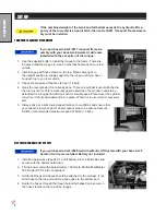
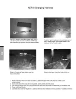
SETUP
The Aerifier arrives from
Smithco
banded on a pallet
.
1. Tow vehicle with 3-point hitch will be needed to transport the Aerifier.
2. If transport package is ordered the tongue hitch will need to be in
-
stalled.
3. Remove tongue from pallet. Install the tongue and place jack in up
-
right position.
4. Crank the jack up so you can hook to tow vehicle.
5. Check the tire pressure. 20 psi (1.4 bar).
6. Check hydraulic fluid level in tank on tow vehicle or the electric/hy
-
draulic lift system if purchased. Install hydraulic fluid as needed.
7. Machine should be greased before starting. See Maintenance part
of manual.
8. Read operating instructions before starting.
9. If using electrical /hydraulic lift system, battery must be installed.
(Battery not included)
Use Automotive type 24F-12 Volt
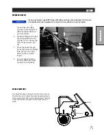
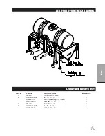
3-POINT HITCH ATTACHMENT
Excessive weight in the ballast tank on the 3-point hitch models will result in the
loss of tow vehicle stability and steering capability. If this occurs front counter
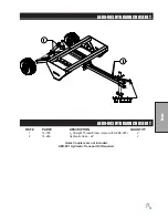
balancing on the tow vehicle or Aer8-001 Transport Frame Assembly must be
installed. Maximum ballast weight is 200 lbs. per ft. of machine width.
1. The Aer-8 must be able to "float". The tractor must be equipped with a "float" position on the lower link
arms. The "float" position will allow the tines to "float" upwards
when an obstruction such as a rock is contacted. This will reduce
tine damage.
2. The Aer-8 must be held in an upright and level position by the jack
legs prior to hitching to a tractor.
3. Back up the tractor until the lower arm ball joints are inside the
frame lift brackets.
4. Install the proper class link pins and quick pins to hold both arms to
the frame.
5. Attach the upper 3-point arm between the center tabs on the frame
and hold in place with the proper class link pin and lynch pin.
6. Once attached to the 3-point, adjust the lower arms so there is no
excessive sway.
Tines are sharp. Keep hands and feet away from reel.
7. Lift the Aer-8 hydraulically and then retract the jack legs.
8. Lower the Aer-8 hydraulically to the ground and adjust the upper 3-point arm
until the Aer-8 column is perpendicular to the ground.
9. From the rear of the aerifier, add water to the ballast tank until the full depth of
the tine penetration is reached. The amount of water used is determined by soil
type, moisture content and amount of compaction present.
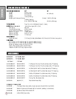
Summary of Contents for AER60-110
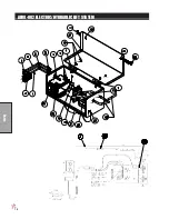
Page 16: ...14 Parts AER8 002 ELECTRIC HYDRAULIC LIFT SYSTEM...
Page 18: ...16 Parts...
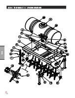
Page 20: ...18 Parts AER 8 TURF QUAKE 5 SPACING DRAWING...
Page 22: ...20 Parts AER 8 TURF QUAKE 7 SPACING DRAWING...
Page 24: ...22 Parts AER 8 ALL STAR 5 SPACING DRAWING...
Page 26: ...24 Parts AER 8 ALL STAR 7 SPACING DRAWING...
Page 28: ...26 Parts AER 8 AERFINE 3 SPACING DRAWING...
Page 30: ...28 Parts AER 8 AERFINE 5 SPACING DRAWING...
Page 32: ...30 Parts AER 8 CORING TINES DRAWING...
Page 34: ...32 Parts REAR ROLLER DRAWING...


