


6
Ser
vice
MAINTENANCE
BATTERY
Batteries normally produce explosive gases which can cause personal injury. Do not allow flames, sparks or
any ignited object to come near the battery. When charging or working near battery, always shield your eyes
and always provide proper ventilation.
Battery cable should be disconnected before using “Fast Charge”.
Charge battery at 15 amps for 10 minutes or 7 amps for 30 minutes. Do not exceed the recommended
charging rate. If electrolyte starts boiling over, decrease charging.
Always remove grounded (-) battery clamp first and replace it last. Avoid hazards by:
1. Filling batteries in well-ventilated areas.
2. Wear eye protection and rubber gloves.
3. Avoid breathing fumes when electrolyte is added.
4. Avoid spilling or dripping electrolyte.
Battery Electrolyte is an acidic solution and should be handled with care. If
electrolyte is splashed on any part of your body, flush all contact areas imme
-
diately with liberal amounts of water. Get medical attention immediately.
Use of booster battery and jumper cables. Particular care should be used
when connecting a booster battery. Use proper polarity in order to prevent
sparks.
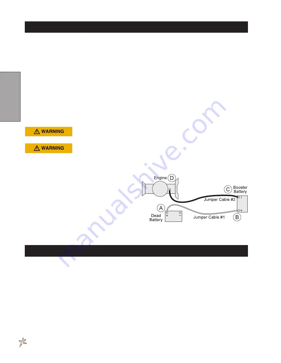
TO JUMP START (NEGATIVE GROUNDED BATTERY):
1. Shield eyes.
2. Connect ends of one cable to positive (+) termi-
nals of each battery, first (A) then (B).
3. Connect one end of other cable to negative (-)
terminal of "good" battery (C).
4. Connect other end of cable (D) to engine block
on unit being started (NOT to negative (-) termi-
nal of battery)
To prevent damage to other electrical components on
unit being started, make certain that engine is at idle speed before disconnecting jumper cables.
STORAGE
If the engine will be out of service for two or more months, use the following storage procedure.
1. Clean the exterior surfaces of the engine.
2. Change the oil and filter while the engine is still warm from operation.
3. The fuel system must be completely emptied, or the gasoline must be treated with a stabilizer to pre-
vent deterioration.
If you choose to use a stabilizer, follow manufacturers recommendations, and add the correct amount
for the capacity of fuel system. Fill fuel tank with clean, fresh fuel. Run engine for 2-3 minutes to get
stabilized fuel into carburetor. Close fuel shut-off valve when unit is being stored or transported.
To empty the system, drain fuel tank and carburetor, or run engine until tank and system are empty.
4. Remove the spark plugs. Add one tablespoon of engine oil into each spark plug hole. Install plugs, but
do not connect the plug leads. Crank the engine two or three revolutions.
5. Store machine in a clean, dry place.
Summary of Contents for 20-700-A
Page 16: ...14 Diagrams HYDRAULIC DIAGRAM Use dielectric grease on all electrical connections ...
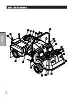
Page 18: ...16 Diagrams BODY FRAME DRAWING ...
Page 20: ...18 Parts NOSE CONE DRAWING ...
Page 22: ...20 Parts NOSE CONE DRAWING ...
Page 24: ...22 Parts LINKAGE DRAWING ...
Page 26: ...24 Parts FRONT AXLE DRAWING ...
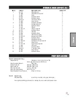
Page 28: ...26 Parts OIL AND FUEL TANK DRAWING ...
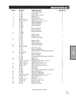
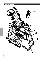
Page 30: ...28 Parts SEAT PANEL DRAWING ...
Page 32: ...30 Parts ENGINE AND PUMPS DRAWING ...
Page 34: ...32 Parts ENGINE AND PUMPS DRAWING ...
Page 36: ...34 Parts SPRAY PUMP DRAWING ...
Page 38: ...36 Parts REAR AXLE DRAWING ...
Page 40: ...38 Parts SPRAY TANK DRAWING ...
Page 42: ...40 Parts TURBO QUAD AGITATOR DRAWING ...
Page 44: ...42 Parts 15 301 ORBITOR DRAWING ...
Page 48: ...46 Parts 76 638 HYDROSTATIC PUMP DRAWING ...
Page 50: ...48 Parts 43 116 REAR WHEEL MOTOR DRAWING ...
Page 58: ...56 Accessories STAR COMMAND I II PLUMBING 15 818 75 Fitting O ring 15 817 50 Fitting O ring ...
Page 61: ...59 Accessories STAR COMMAND I WIRING 10 638 Fiberglass Cover 10 716 Dynajet Cover ...
Page 68: ...66 Accessories NOTES ...
Page 70: ...68 Accessories 17 580 20 HEAVY BOOM ...
Page 72: ...70 Accessories 17 580 20 BOOM DRAWING ...
Page 78: ...76 Accessories 17 585 18 HD BOOM DRAWING ...
Page 80: ...78 Accessories 17 585 18 HD BOOM DRAWING ...
Page 84: ...82 Accessories 17 601 15 HD BOOM DRAWING ...
Page 86: ...84 Accessories 17 601 15 HD BOOM DRAWING ...
Page 96: ...94 Accessories 30 010 ELECTRIC HOSE REEL DRAWING ...
Page 100: ...98 Accessories HOSE REEL MOUNT DRAWING ...
Page 102: ...100 Accessories 30 004 FOAM MARKER DRAWING WIRING DRAWING Spray Star 3180 Spray Star 2000 ...
Page 104: ...102 Accessories FOAMER NOZZLE MOUNT HOSE GUARD MOUNT DRAWING ...
Page 106: ...104 Accessories 14 291 FOAMER REPLACEMENT PARTS ...
Page 112: ...110 Accessories 15 620 CHEMICAL CLEAN LOAD PARTS DRAWING ...
Page 116: ...114 Reference NOTES ...


