


8
Ser
vice
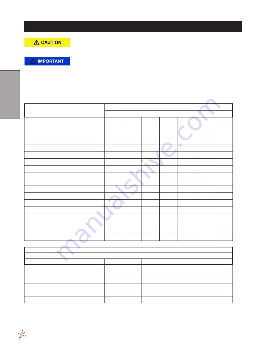
SERVICE CHART
Before servicing or making adjustments to the machine, stop engine, block
wheels and remove key from ignition.
Follow all procedures and ONLY use parts prescribed by the manufacturer.
Read the engine manual before maintenance.
The suggested maintenance checklist is not offered as a replacement for the manufacturer’s engine manual
but as a supplement. You must adhere to the guidelines established by the manufacturer for warranty cover-
age. In adverse conditions such as dirt, mud or extreme temperatures, maintenance should be more frequent.
Duplicate this page for routine use
Maintenance Check Item
For the week of:
Mon
Tues.
Wed.
Thurs.
Fri.
Sat.
Sun.
Check the Safety Seat Switch
Check Steering Operation
Check the fuel level
Check the engine oil level.
Check the condition of the air filter
Clean the engine cooling fins.
Check for unusual engine noises
Check the hydraulic oil level
Check hydraulic hoses and fittings for damage
Check for fluid leaks.
Check the tire pressure (20-30 psi)
Check the Instrumentation
Inspect electrical system for frayed wires
Check neutral start
Change oil filter.
Change oil.
Lubricate Machine and Booms
Ensure all warning decals are intact.
Areas of Concern
Inspection Performed by:
Item
Date
Information
Summary of Contents for 20-700-A
Page 16: ...14 Diagrams HYDRAULIC DIAGRAM Use dielectric grease on all electrical connections ...
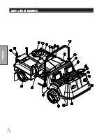
Page 18: ...16 Diagrams BODY FRAME DRAWING ...
Page 20: ...18 Parts NOSE CONE DRAWING ...
Page 22: ...20 Parts NOSE CONE DRAWING ...
Page 24: ...22 Parts LINKAGE DRAWING ...
Page 26: ...24 Parts FRONT AXLE DRAWING ...
Page 28: ...26 Parts OIL AND FUEL TANK DRAWING ...
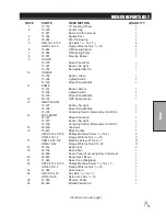
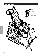
Page 30: ...28 Parts SEAT PANEL DRAWING ...
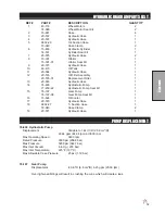
Page 32: ...30 Parts ENGINE AND PUMPS DRAWING ...
Page 34: ...32 Parts ENGINE AND PUMPS DRAWING ...
Page 36: ...34 Parts SPRAY PUMP DRAWING ...
Page 38: ...36 Parts REAR AXLE DRAWING ...
Page 40: ...38 Parts SPRAY TANK DRAWING ...
Page 42: ...40 Parts TURBO QUAD AGITATOR DRAWING ...
Page 44: ...42 Parts 15 301 ORBITOR DRAWING ...
Page 48: ...46 Parts 76 638 HYDROSTATIC PUMP DRAWING ...
Page 50: ...48 Parts 43 116 REAR WHEEL MOTOR DRAWING ...
Page 58: ...56 Accessories STAR COMMAND I II PLUMBING 15 818 75 Fitting O ring 15 817 50 Fitting O ring ...
Page 61: ...59 Accessories STAR COMMAND I WIRING 10 638 Fiberglass Cover 10 716 Dynajet Cover ...
Page 68: ...66 Accessories NOTES ...
Page 70: ...68 Accessories 17 580 20 HEAVY BOOM ...
Page 72: ...70 Accessories 17 580 20 BOOM DRAWING ...
Page 78: ...76 Accessories 17 585 18 HD BOOM DRAWING ...
Page 80: ...78 Accessories 17 585 18 HD BOOM DRAWING ...
Page 84: ...82 Accessories 17 601 15 HD BOOM DRAWING ...
Page 86: ...84 Accessories 17 601 15 HD BOOM DRAWING ...
Page 96: ...94 Accessories 30 010 ELECTRIC HOSE REEL DRAWING ...
Page 100: ...98 Accessories HOSE REEL MOUNT DRAWING ...
Page 102: ...100 Accessories 30 004 FOAM MARKER DRAWING WIRING DRAWING Spray Star 3180 Spray Star 2000 ...
Page 104: ...102 Accessories FOAMER NOZZLE MOUNT HOSE GUARD MOUNT DRAWING ...
Page 106: ...104 Accessories 14 291 FOAMER REPLACEMENT PARTS ...
Page 112: ...110 Accessories 15 620 CHEMICAL CLEAN LOAD PARTS DRAWING ...
Page 116: ...114 Reference NOTES ...


