IR lamp control module - HELCON 11XX series -
Installation, use and maintenance manual - EN
Ver. 1.02
21
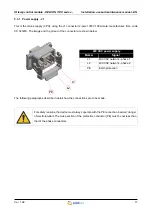
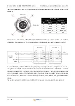
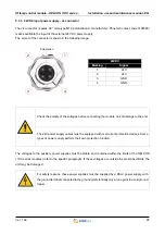
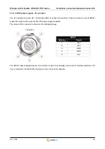
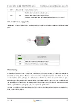
The following illustration shows the pinout of the same (the image shows the connector J2, the connector J3 is
the same).
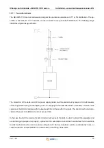
The connections must be made with suitable cables for RS485 serial lines (shielded and with at least one twist-
ed pair with 120Ω impedance for the differential signals); the following image shows an example of wiring.
To avoid reflections, which are detrimental to signal quality, especially in the case of long distances, it is nec-
essary to connect a 120Ω termination resistor to the end of the line. To facilitate this termination, the resistor is
integrated into the KF131326 connector, to be connected to the J4 connector. The termination at the beginning
of the line is usually integrated into the master device. The ground connection (GND), although not essential
for functional reasons, is however recommended to improve the immunity of the system against EMC distur-
bances.
The auxiliary address line (ADDR_IN and ADDR_OUT) is reserved for automatic address assignment.
1
4
2
FLxIO field bus
J2 (input)
J3 (output)
Pin
Signal
Pin
Signal
1
DATA+
1
DATA+
2
GND
2
GND
3
DATA-
3
DATA-
4
ADDR_IN
4
ADDR_OUT
5
NC
5
NC
3
5
Polarization
Polarization
MODULE #1
MODULE #N
SHIELD
SHIELD
MASTER
FLxIO
DATA+
GND
ADDR_OUT
DATA-
DATA+
GND
ADDR_OUT
DATA-
DATA+
GND
ADDR_OUT
DATA-
DATA+
GND
ADDR_IN
DATA-
SHIELD
DATA+
GND
ADDR_IN
DATA-
J2
J2
J3
J3
120Ω

