Smeg SCD60CMX8 Manual Download Page 8

10

Instructions for the user

4.1

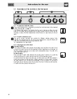
Description of the controls on the front panel

4.1.1 Temperature selection knob

The cooking temperature is selected by turning the knob clockwise to the required
setting, between 

50°

 and 

260°C

.

The indicator light comes on to indicate that the oven is heating up. When this light
goes out, the preset heating temperature has been reached. When the light flashes
regularly, it means that the temperature inside the oven is kept steady on the set
level.

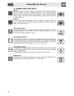
4.1.2 Function selection knob

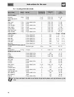
The oven's various functions are suitable for different cooking modes. After
selecting the required function, set the cooking temperature using the thermostat
knob. For more information on cooking functions, see: 
“8. COOKING WITH THE OVEN”.

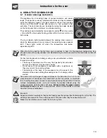
4.1.3 Cooking zone control knob

Standard heating

The circle next to each knob indicates the cooking zone it controls. To switch a zone
on, press the knob and turn it to the required position. Adjustment is continuous, so
that the appliance functions even when set to intermediate values. To switch off a
zone, return the knob to 0.

Double heating

The circle next to each knob indicates the cooking zone it controls. To switch the
inner cooking zone on, press the knob and turn it to the required position.
To switch on both the inner and outer zone, turn the knob to   / 

 then release it.

The knob will return to the maximum intensity position for the hot plate. To adjust
the heat intensity, turn the knob anti-clockwise to the 0 position. To go back to
heating the inner zone only, return the knob to 0 then turn it to the required position.
To switch off a zone, return the knob to 0.

Summary of Contents for SCD60CMX8

Page 1: ...9 9 2 Ordinary daily cleaning 19 9 3 Food stains or residues 19 9 4 Cleaning the glass ceramic hob 20 9 5 Weekly cleaning 20 9 6 Cleaning the oven 21 10 EXTRAORDINARY MAINTENANCE 22 10 1 Replacing the...

Page 2: ...ed in an exposed position either in the drawer where present or on the back of the appliance A copy of the identification plate is included in the booklet It should be applied to the appropriate space...

Page 3: ...e sharp Take care that no objects are stuck in the door of the oven Do not open the storage compartment where present when the oven is on and still hot The temperatures inside it may be very high If t...

Page 4: ...ted to the power supply cable and its socket must be of the same type and conform to the standards in force The socket must be accessible after the appliance has been installed Never disconnect the pl...

Page 5: ...never put water on them Place the lid on the saucepan and turn off the cooking zone Take care when using additional electrical appliances in the kitchen e g blender toaster etc Connection cables must...

Page 6: ...o the application of administrative sanctions The appliance does not contain substances in quantities sufficient to be considered hazardous to health and the environment in accordance with current Eur...

Page 7: ...ons for the user 4 GET TO KNOW YOUR APPLIANCE Cooking hob Control panel Oven seal Oven light double on some models Door sensor on some models only Rack tray support frame Fan Roof liner on some models...

Page 8: ...functions see 8 COOKING WITH THE OVEN 4 1 3 Cooking zone control knob Standard heating The circle next to each knob indicates the cooking zone it controls To switch a zone on press the knob and turn i...

Page 9: ...esserts Scraper useful for cleaning the glass ceramic hob Do not use on other surfaces The oven accessories intended to come into contact with food are made of materials that comply with the provision...

Page 10: ...wn in the figure at the side To remove the rack or tray lift the front slightly The mechanical lock or the extension piece where present must always face the back of the oven Gently insert racks and t...

Page 11: ...does not absorb odours For best cooking results and energy saving only use containers suitable for electric cooking The bases of containers must be very thick perfectly flat and clean and dry The hob...

Page 12: ...en runners The oven features 5 runners for positioning trays and racks at different heights The insertion heights are indicated from the bottom upwards see figure models with frames models with guides...

Page 13: ...vent any steam in the oven from causing problems open the door in two stages keep it half open 5 cm approx for 4 5 seconds and then fully open To access food always leave the door open as short a time...

Page 14: ...he grill grilling perfectly even very thick foods Perfect for large cuts of meat e g shin of pork We recommend using the 4th runner FAN ASSISTED BOTTOM The combination of the fan with just the lower h...

Page 15: ...temperature and the cooking duration depend on the quality and consistency of the dough Check whether the dessert is cooked right through at the end of the cooking time put a toothpick into the highes...

Page 16: ...l 3 250 9 11 9 11 Liver slices Fan assisted grill 4 250 2 3 2 3 Sausages Fan assisted grill 3 250 7 9 5 6 Meatballs Fan assisted grill 3 250 7 9 5 6 ROTISSERIE MEAT where present Chicken Rotisserie gr...

Page 17: ...less steel in good condition it should be cleaned regularly after use Let it cool first 9 2 Ordinary daily cleaning To clean and preserve stainless steel surfaces always use only specific products tha...

Page 18: ...e not alterations to the material of the hob but just residues which have not been removed and have then carbonised Shiny surfaces can form due to the bases of saucepans especially aluminium ones rubb...

Page 19: ...he inside of the oven to unhook it from its housing A then slide it out of the seats at the back B 2 When cleaning is complete repeat the above procedures to put the guide frames back in 9 6 2 Cleanin...

Page 20: ...g guide frames where present Then remove the bulb cover using a tool e g a screwdriver Remove the bulb by unscrewing filament bulbs or pulling it out halogen bulbs in the indicated direction Replace t...

Page 21: ...is operation may have to be repeated during the glass removal process if the door is accidentally freed Removing the internal glass panel Remove the internal glass panel by pulling the rear part gentl...

Page 22: ...on the type of installation this appliance belongs to class 2 subclass 1 Fig A Fig B or to class 1 Fig C It may be installed next to walls one of which must be higher than the worktop at a minimum di...

Page 23: ...tandards The socket must be accessible after the appliance has been built in NEVER UNPLUG BY PULLING ON THE CABLE Should the earthing wire need replacing it must be longer than the conducting wires so...

Page 24: ...appliance 1 Unscrew the 2 nuts B on the back of the worktop 2 Position the skirt above the worktop taking care to align the pins C with the holes D 3 Secure the skirt to the worktop by tightening scre...

Reviews: