-7-
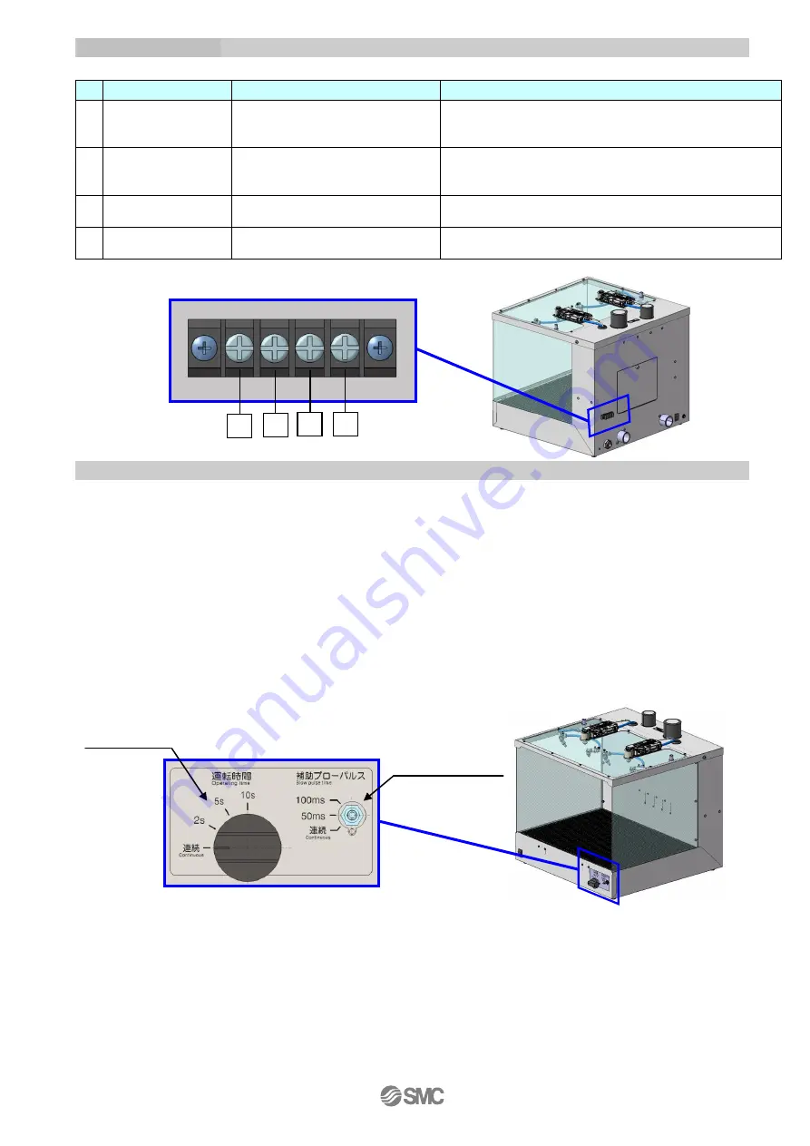
Operation time
set switch
Additional air flow
pulse operation time
set switch
1.4 Terminal Block
*1: This output signal shows that the main circuit is ON. This does NOT show the operation status of the ionizer.
1.5 Operation Method
Refer to "2.3 Construction" for descriptions of each part.
1. Turn ON the main power supply switch and the dust collector switch after confirming safety guidelines
are met.
Make sure the exhaust port is directed away from objects or operaters. The dust collector discharges
adsorbed substances from the exhaust port at a high speed.
2. Supply pressure of 0.4 to 0.8 MPa (recommended values) to the piping that is connected (by opening
the valve or regulator prepared by user). Adjust the pressure of the regulator connected to the air flow
adjustment to be within the range of 0.1 to 0.3MPa Adjust the pressure of the regulator connected to the
the dust collector to be within the range of 0.3 to 0.5 MPa.
3. Set the operation time of the desktop duster box using the Operation time set switch. The operation time
can be selected from continuous, 2 second, 5 seconds, or 10 seconds.
4. Set the additional air flow pulse operation time with the Additional air flow pulse operation time set switch.
The operation time can be selected from continuous (no pulse), 50ms, or 100ms.
5. Check the actual static and dust eliminating condition of the workpiece.
When the additional air flow is too strong, adjust the pressure or air flow rate by rotating the handle of the
regulator connected to the air flow adjustment or the additional air flow adjusting restrictor (option).
6. When not using the dust collector, turn the switch off.
No.
Terminal
Input/Output specifications
Remarks
1
Operation signal
output
Transistor output: 0.1A, 5 to 24 VDC
Connect the cable (that is prepared by the user) to this
terminal to output a signal while the desktop duster box is
operating.
*1
2
External input
+24 VDC
When an external signal is used for starting operation
instead of a photoelectric sensor, connect an external switch
to this terminal.
3
COM
+
1: Connect the cable (that is prepared by the user) when the
operation signal output is used.
4
COM
-
2: Connect the cable (that is prepared by the user) when the
external input is used.
1
2
3
4


