

3.4 Mounting
If air leakage increases or equipment does not operate properly,
stop operation
After mounting or maintenance, etc., connect the compressed air and power sup
plies, and perform appropriate function and leakage inspections to confirm that the
unit is mounted properly.
Instruction manual
Mount and operate the product after reading the manual carefully and
understanding its contents. Also keep the manual where it can be referred to as
necessary.
Painting and coating
Warnings or specifications printed or pasted on the product should not be erased,
removed or covered up.
3.5 Lubrication
CAUTION:
SMC products have been lubricated for life at manufacturer, and do not require
lubrication in service.
If a lubricant is used in the system, use turbine oil Class 1(no additive), ISO VG32.
Once lubricant is used in the system, lubrication must be continued because the
original lubricant applied during manufacturing will be washed away.
4
MAINTENANCE
WARNING:
Not following proper procedures could cause the product to malfunction and
could lead to damage to the equipment or machine.
If handled improperly, compressed air can be dangerous. Assembly, handling and
repair of pneumatic system should be performed by qualified personnel only.
Drain: remove condensate from the filter bowl on a regular basis.
Shut-down before maintenance: before attempting any kind of maintenance
make sure the supply pressure is shut off and all residual air pressure is released
from the system to be worked on.
Start-up after maintenance: apply operating pressure and power to the
equipment and check for proper operation and possible air leaks. If operation is
abnormal, please verify product set-up parameters.
Do not make any modification to the product
Do not disassemble the product, unless required by installation or maintenance
instructions.
Maintenance procedures are shown in the operation manual.
If maintenance is not properly done, it may cause malfunction and damage of
machine or equipment.
Machine maintenance and supply/exhaust of compressed air.
When machine is to be serviced, first check for removal of work pieces and run-
away of equipment, etc. Then cut the supply pressure and power, and exhaust
compressed air in the system through residual pressure release mechanism.
When the machine is to be released, check first that actuators are in their proper
start up position.
Low frequency position.
Valves should be switched at least once every 30 days to avoid malfunction.
(Pay attention to air supply)
N.C./N.O. Conversion
To convert valve operation from N.C. to N.O. or N.O. to N.C., remove the pilot valve,
move the function plate along the gasket, both top and bottom until the mark > meets
N.C. (N.O.)
Please note however, that the N.O. valve functions properly only when the appropriate
pressure is applied to the valve.
Piping (Vacuum Use)
1. Piping in general:
EXH port = Vacuum pump/Blower} (Suction side)
OUT port = Vacuum pad/Tank} (Load side)
IN port = Plug (2 port valve), Air releasing, Air pressure-in
2. Following the above piping, vacuum passage is switched between OUT and EXH,
therefore, N.C./N.O. indication on the function plate and switching of the vacuum
passage are reversed; N.C. (Normally closed) in vacuum passage are reversed:
"N.C." indicated on the plate
→
N.O. in vacuum passage (Normally open)
"N.O." indicated on the plate
→
N.C. in vacuum passage (Normally closed)
5
LIMITATIONS OF USE
WARNING:
Do not exceed any of the specifications laid out in section 2 of this document or
the specific product catalogue.
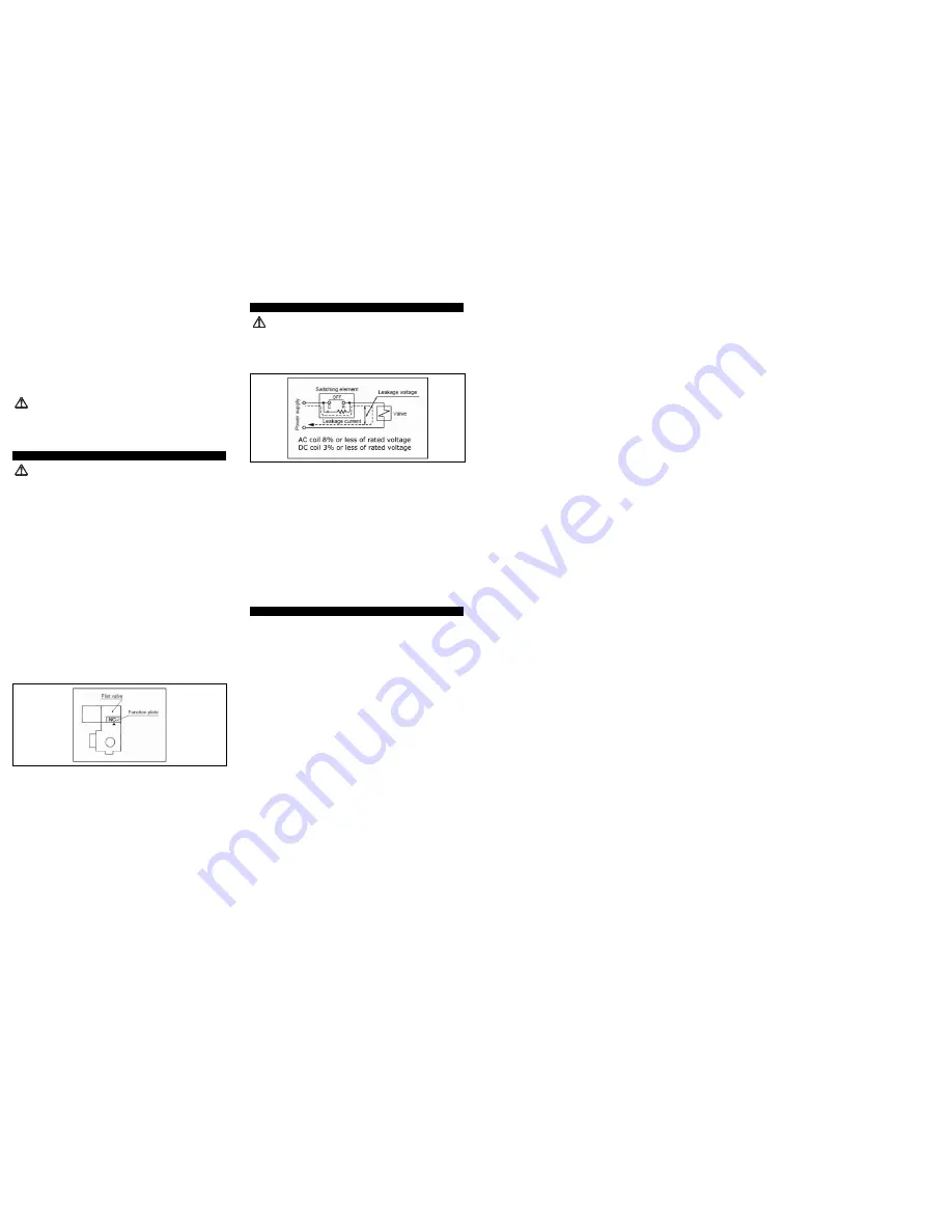
Leakage voltage
Particularly when using a C-R element (surge voltage suppressor) for protection
of the switching element, take note that leakage voltage will increase due to
leakage current flowing through the C-R element, etc.
Drive the solenoid valve for AC with SSR or triac output.
a)
Leak current:
If output element's surge circuit has C-R element, slight current flows even
if turned OFF. This causes malfunction on valve reset. When the valve goes
over allowable value shown above, install bleeder resistance.
b)
Minimum load capacity (minimum load current)
When valve consumption current is less than minimum load capacity of
output element, or when the margin is small, output element sometimes
cannot change itself. Please consult SMC.
Surge voltage suppressor
If a surge protection circuit contains non-ordinary diodes such as Zener diodes or
ZNRs, a residual voltage that is in proportion to the protective elements and the
rated voltage will remain. Therefore, give consideration to surge voltage
protection of the controller. In the case of diodes, the residual voltage is
approximately 1V.
Low temperature operation
Avoid ambient temperatures outside the range of -10 to 60°C (-5°C minimum for
rubber seals). At low temperatures, appropriate measures should be taken to
avoid solidification or freezing of drainage and moisture, etc.
Mounting direction
All mounting postures are available
6
EUROPEAN CONTACT LIST
6.1 SMC Corporation
Country
Telephone
Country
Telephone
Austria
(43) 2262-62 280
Italy
(39) 02-92711
Belgium
(32) 3-355 1464
Netherlands
(31) 20-531 8888
Czech Republic
(420) 5-414 24611
Norway
(47) 67 12 90 20
Denmark
(45) 70 25 29 00
Poland
(48) 22-548 50 85
Finland
(358) 9-859 580
Portugal
(351) 22 610 89 22
France
(33) 1-64 76 1000
Spain
(34) 945-18 4100
Germany
(49) 6103 4020
Sweden
(46) 8 603 12 00
Greece
(30) 1- 342 6076
Switzerland
(41) 52-396 3131
Hungary
(36) 23 511 390
Turkey
(90) 212 221 1512
Ireland
(353) 1-403 9000
United Kingdom
(44) 1908-56 3888
6.2 Websites
SMC Corporation
www.smcworld.com
SMC Europe
www.smceu.com
VP3000*-TFJ0003


