


SGH100-TFM86
Installation and Maintenance Manual
Coolant Valve
Series : SGH100/200/300/400
1 Safety Instructions
• This manual contains essential information for the protection of users
and others from possible injury and/or equipment damage.
• Read this manual before using the product, to ensure correct handling,
and read the manuals of related apparatus before use.
• Keep this manual in a safe place for future reference.
• These instructions indicate the level of potential hazard by label of
“DANGER”, “WARNING” or “CAUTION”, followed by important safety
information which must be carefully followed.
• To ensure safety of personnel and equipment the instructions in this
manual and the product catalogue must be observed, along with other
relevant safety practices.
WARNING
• The compatibility of pneumatic equipment is the responsibility of
the person who designs the pneumatic system or decides its
specifications.
Since the product specified here is used under various operating
conditions, its compatibility with specific equipment must be decided by
the person who designs the equipment or decides its specifications
based on necessary analysis and test results. The expected
performance and safety assurance of the equipment will be the
responsibility of the person who has determined its compatibility with
the product. This person should also continuously review all
specifications of the product referring to its latest catalog information,
with a view to giving due consideration to any possibility of equipment
failure when configuring the equipment.
• Only trained personnel should operate pneumatically operated
machinery and equipment.
The product specified here may become unsafe if handled incorrectly.
The assembly, operation and maintenance of machines or equipment
including our products must be performed by an operator who is
appropriately trained and experienced.
• Do not service machinery/equipment or attempt to remove
components until safety is confirmed.
1) The inspection and maintenance of machinery/equipment should
only be performed after measures to prevent falling or prevention of
the danger by the fluid have been confirmed.
2) When the product is to be removed, confirm that the safety measures
as mentioned above are implemented and the power from any
appropriate source is cut, and read and understand the specific
product precautions of all relevant products carefully.
3) Before machinery/equipment is restarted, take measures to prevent
unexpected operation and malfunction.
• Contact SMC beforehand and take special consideration of safety
measures if the product is to be used in any of the following
conditions.
1) Conditions and environments beyond the given specifications, or if
product is used outdoors or with direct sunlight.
2) With fluids whose application causes concern due to the type of fluid
or additives, etc.
1 Safety Instructions (continued)
3) An application that has the possibility of having negative effects on
people, property, or animals, requiring special safety analysis.
1. The product is provided for use in manufacturing industries.
The product herein described is basically provided for peaceful use in
manufacturing industries.
If considering using the product in other industries, consult SMC
beforehand and exchange specifications or a contract if necessary.
If anything is unclear, contact your nearest sales branch.
Limited warranty and Disclaimer/Compliance Requirements
The product used is subject to the following “Limited warranty and
Disclaimer” and “Compliance Requirements”.
Read and accept them before using the product.
Limited warranty and Disclaimer
1. The warranty period of the product is 1 year in service or 1.5 years after
the product is delivered.
*3
)
Also, the product may have specified durability, running distance or
replacement parts. Please consult your nearest sales branch.
2. For any failure or damage reported within the warranty period which is
clearly our responsibility, a replacement product or necessary parts will
be provided. This limited warranty applies only to our product
independently, and not to any other damage incurred due to the failure
of the product.
3. Prior to using SMC products, please read and understand the warranty
terms and disclaimers noted in the specified catalog for the particular
products.
*3) Vacuum pads are excluded from this 1 year warranty.
A vacuum pad is a consumable part, so it is warranted for a year after it
is delivered. Also, even within the warranty period, the wear of a product
due to the use of the vacuum pad or failure due to the deterioration of
rubber material are not covered by the limited warranty.
CAUTION
• Ensure that the air supply system is filtered to 5 micron.
2 Specifications
2.1 Valve specifications
Note :
Impact resistance:
No malfunction occurred when it was tested with a drop
tester in the axial direction and at right angles to the main valve & armature;
in both energized & de-energised states and for every time in each condition
(Values at the initial period.)
Vibration resistance:
No malfunction occurred in a one-sweep test between
45 and 2000 Hz. Tests ere performed at both energized and de-energized
states in the axial direction and at right angles to the main valve & armature.
(Valves at the initial period.)
2.2 Solenoid Specifications
2 Specifications (continued)
Note) In common between 110 VAC and 115 VAC, and between 220 VAC and 230 VAC.
For 115 VAC and 230 VAC, the allowable voltage is -15% to +5% of rated
voltage.
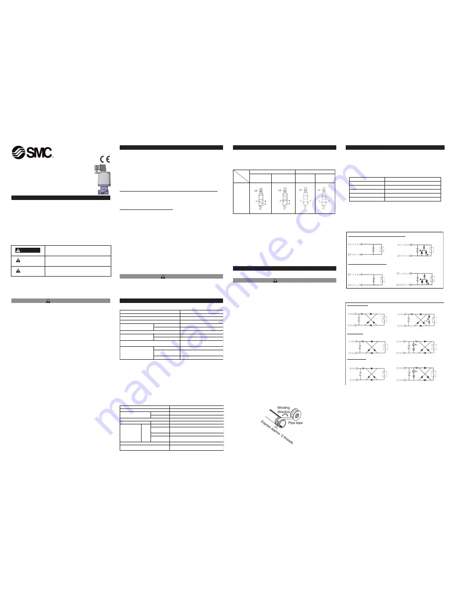
2.3 Circuit symbol
Note)
The Reverse pressurization type valve can be used as a N.C. valve or as a Selector
valve. See below for piping method:
•
N.C. valve use
1 port : output port
2 port : waste fluid port
3 port : supply port
•
Selector valve use 1 port : output port
2 port : low pressure supply port
3 port : high pressure supply port
3 Installation
3.1 Environment
WARNING
1. Do not use in an environment where the product is directly exposed to
corrosive gases, chemicals, salt water, water or steam.
2. Products with IP65 and IP67 enclosures (based on IEC60529) are
protected against dust and water, however, these products cannot be used
in water.
3. Incorrect mounting of the product violates the IP65 rating. Be sure to read
the Precautions for each product.
4. Do not use in explosive atmospheres.
5. The product should not be exposed to prolonged sunlight. Use a protective
cover.
6. Do not mount the product in a location where it is subject to strong
vibrations and/or shock. Check the product specifications.
7. Remove emissive heat.
8. If using in an atmosphere where there is possible contact with water
drop-lets, oil, weld spatter, etc., take suitable preventative measures.
9. When the product is mounted in a control panel, or when it's energized for
a long time, make sure that the ambient temperature is within the specified
range.
3.2 Piping
1. Preparation before piping
Before piping is connected, it should be thoroughly blown out with air
(flushing) or washed to remove chips, cutting oil and other debris from
inside the pipe.
Install piping so that it does not apply pulling, pressing, bending or other
forces the valve body.
2. Sealant tape
When installing piping or fitting into a port, ensure that sealant material
does not enter the port internally. Furthermore, when sealant tape is
used, leave 1.5 to 2 thread ridges exposed at the end of the threads.
<For AC>
3 Installation (continued)
3. Avoid connection of ground lines to piping, as this may cause electric
corrosion of the system.
4. Always tighten threads with the proper tightening torques.
When screwing fittings into valves, tighten with the proper tightening
torque shown below.
Tightening Torque for Piping
5. Connection of piping to products.
When connecting piping to a product, avoid mistakes regarding the
supply port, etc.
3.3 Light/Surge Voltage Suppressor
<For DC>
In extreme conditions, there is a possibility of
serious injury or loss of life.
WARNING
If instructions are not followed there is a
possibility of serious injury or loss of life.
CAUTION
If instructions are not followed there is a
possibility of injury or equipment damage.
DANGER
t
r
o
p
2
t
r
o
p
3
1port
pressurization
Reverse
pressurization
N.C. N.O.
External
pilot
solenoid
type
0
0
4
/
0
0
3
/
0
0
2
/
0
0
1
H
G
S
e
p
y
T
t
n
a
l
o
o
C
d
i
u
l
f
g
n
i
t
a
r
e
p
O
Fl
u
id temperat
u
re
°
)
g
n
i
z
e
e
r
f
o
N
(
0
6
o
t
5
-
C
Am
b
ient temperat
u
re
°
C
-5 to 50 (
N
o freezing)
SGH
A,B-30
4.5
Proof press
u
re
MPa
SGH
A,B-70
10.5
Leakage from the
v
al
v
e seat
100cm
3
/min of less (
w
ater press
u
re)
SGH
A,B-30
0 to 3
Operating press
u
re range
MPa
SGH
A,B-70
0 to 7
Man
u
al o
v
erride
N
on-locking type, p
u
sh t
u
rn-
locking slotted type
Press
u
re MPa
0.25 to 0.7
L
ub
rication
N
ot re
qu
ired (Use t
u
r
b
ine oil Class 1
(ISO
V
G32), if l
ub
ricated.
External pilot
Temperat
u
re
°
C
-5 to 50 (
N
o freezing)
! !
!
! !
!
! !
!
! !
!
Connection thread
Appropriate tightening tor
qu
e (
N
•
m)
9
o
t
7
8
/
1
4
2
o
t
2
2
8
/
3
0
3
o
t
8
2
2
/
1
0
3
o
t
8
2
4
/
3
8
3
o
t
6
3
1
Cond
u
it terminal, DI
N
terminal (non-polar type)
S
u
rge
v
oltage s
u
ppressor (TS/DS) Light/s
u
rge
v
oltage s
u
ppressor(TZ,DZ)
M12 connector (non-polar type)
S
u
rge
v
oltage s
u
ppressor(
W
S/
V
S) Light/s
u
rge
v
oltage s
u
ppressor(
W
Z/
V
Z)
Coil
Varistor
Coil
Varistor
Varistor
Varistor
Coil
Coil
Cond
u
it terminal
S
u
rge
v
oltage s
u
ppressor(TS) Light/s
u
rge
v
oltage s
u
ppressor(TZ)
DI
N
terminal
S
u
rge
v
oltage s
u
ppressor(DS) Light/s
u
rge
v
oltage s
u
ppressor(DZ)
M12 connector
S
u
rge
v
oltage s
u
ppressor(
W
S/
V
S) Light/s
u
rge
v
oltage s
u
ppressor(
W
Z/
V
Z)
li
o
C
li
o
C
V
aristor
V
aristor
V
aristor
V
aristor
li
o
C
li
o
C
r
o
t
s
i
r
a
V
r
o
t
s
i
r
a
V
li
o
C
li
o
C
Pilot solenoid
v
al
v
e specification
V
116-
-1
r
o
t
c
e
n
n
o
c
2
1
M
,
l
a
n
i
m
r
e
t
N
I
D
,
l
a
n
i
m
r
e
t
t
i
u
d
n
o
C
y
r
t
n
e
l
a
c
i
r
t
c
e
l
E
DC 12
V
, 24
V
Coil rated
v
oltage
AC(50/60Hz) 100
V
, 110
V
, 200
V
, 220
V
Allo
w
a
b
le
v
oltage fl
u
ct
u
ation ±10
%
of rated
v
oltage
N
ote)
Po
w
er cons
u
mption
W
DC
0.35
(
W
ith indicator light : 0.5
8
)
100
V
0.7
8
(
W
ith indicator light : 0.
8
7)
110
V
[115
V
]
0.
8
6 (
W
ith indicator light : 0.97)
0.94 (
W
ith indicator light : 1.07)
200
V
1.15
(
W
ith indicator light : 1.30)
Apparent
v
oltage
V
A
AC
220
V
[230
V
]
1.27 (
W
ith indicator light : 1.46)
1.39 (
W
ith indicator light : 1.60)
S
u
rge
v
oltage s
u
ppressor Z
N
R (
V
aristor)
Indicator light
LED (
N
eon
bu
l
b
w
hen AC
w
ith DI
N
terminal
and M12 connector)
! !
!
Table 1.
Table 3.
Table 2.
Table 4.
Figure 2.
Figure 3.
Figure 1.


