background image


Doc. no.IZ

-OMV0005 


6) Do not allow foreign matter or tool to enter the ionizer nozzle. 

The emitter is installed in the nozzle. If conductive objects such as metal tools or the human body either 

contacts or comes close to the emitter, reaction to electric shock can lead to further injuries due to collision 
with  surrounding  equipment.    Also,  if  the  tool  damages  the  emitters,  it  may  interfere  with  the  specified 
function and performance, and may also cause operation failure or an accident. 


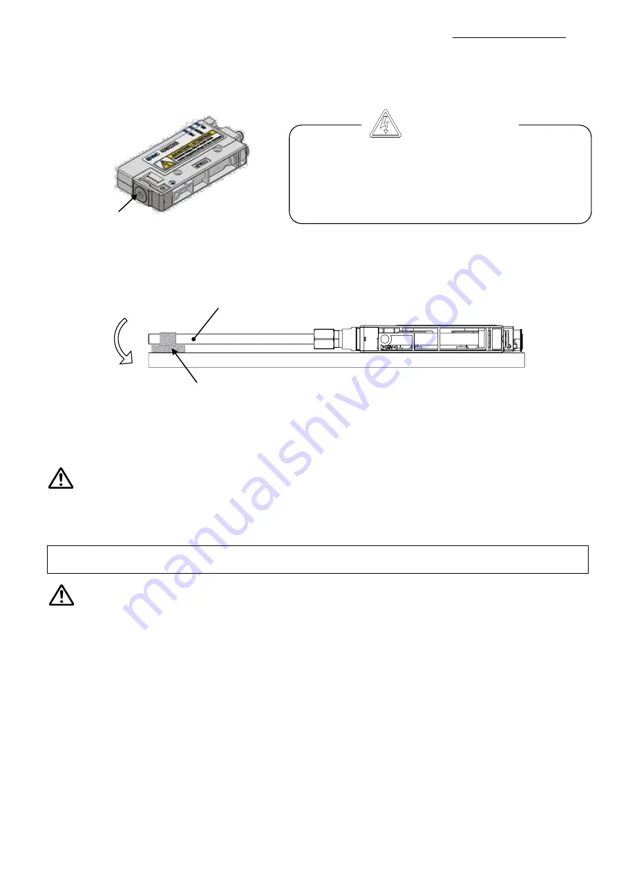
7) Avoid applying moment to the nozzle.   

A moment may be applied to the nozzle depending on the shape or length of the nozzle mounted to the 

female threads for piping. It is possible that the nozzle or body will be damaged. 

If a moment force of more than 0.05 Nm is applied, the middle of the nozzle should be supported so that the 

nozzle does not receive the moment. 


8) Do not adhere tape or labels onto the product body. 

If the tape or label contains conductive adhesive or reflective paint, it is possible that due to the dielectric 

effect, charge could build up causing an electro-static discharge or electrical leakage. 

9) Ensure that both the power supply and compressed air supply are disconnected before commencing 

with the product installation. 


1) Make sure to confirm the effect of static neutralization after installation. 

The  effect  of  the  static  neutralization  varies  depending  on  the  surrounding  installation  and  operating 

conditions. Confirm the effect of the static neutralization after installation. 


1) Before wiring, ensure that the power supply capacity meets the specification and that the voltage is 

within the specification. 

2) To maintain product performance, the power supply should be UL Class 2 certified by National Electric 

Code (NEC) or evaluated as a limited power source according to UL60950. 

3) To maintain the product performance, ground the product with an earth ground cable with a resistance 

of 100 Ω or less according to this manual. 

4) Remove the power supply before wiring (including the connector plug in/out). 
5) Ensure the safety of wiring and surrounding conditions before supplying power. 
6)  Do  not  connect  or  disconnect  the  connectors  (including  power  source)  while  the  power  is  being 

supplied. Failure to follow this procedure may cause product malfunction. 

7) Malfunctions stemming from noise may occur if the wire is installed in the same route as that of power 

or high-voltage cable. Route the Ionizer wires separately. 

8) Confirm that there is no error in wiring before operation. Incorrect wiring will lead to product damage or 

malfunction. 

9) Flush the piping before connecting. Verify that all dust, moisture, oil, etc. are eliminated from the piping 

before connecting. 

Wiring and Piping 


Caution


Warning


High voltage is applied to the emitters. Never touch the 

electrodes.  Inserting  foreign  matter  into  the  cartridge  or 
touching  electrode  may  cause  electrical  shock  and 
instantaneous  rapid  body  motion  to  escape  from  the 
shock.  Your  body  may  then  touch  the  equipment  around 
you, causing injury. 

Danger High voltage


Nozzle 

Nozzle 

To hold the nozzle 

Moment 

Summary of Contents for IZN10E Series

Page 1: ...Traffa Schneller Abbau statischer Elektrizit t Bedienungsanleitung D senausf hrung Serie IZN10E...

Page 2: ...Doc no IZ OMV0005 1 PRODUCT NAME Ionizer Nozzle type MODEL Series IZN10E Series...

Page 3: ...llation 13 3 1 2 Ionizer Body Installation 14 3 2 Wiring 17 3 2 1 Connection Circuit 17 3 2 2 Wiring of the power supply cable 19 3 2 3 Ground connection 19 3 2 4 AC adapter 19 3 3 Timing chart 20 4 F...

Page 4: ...equipment failure when configuring the equipment 2 Only personnel with appropriate training should operate machinery and equipment The product specified here may become unsafe if handled incorrectly...

Page 5: ...e failure of the product 3 Prior to using SMC products please read and understand the warranty terms and disclaimers noted in the specified catalog for the particular products 2 Vacuum pads are exclud...

Page 6: ...inspection and wiring To avoid applying unreasonable stress to the connector and one touch fitting ensure any bends in the cable or air tubing are greater than the minimum bending radius If the cable...

Page 7: ...onfirm the effect of the static neutralization after installation 1 Before wiring ensure that the power supply capacity meets the specification and that the voltage is within the specification 2 To ma...

Page 8: ...se damage to this product These may cause an electric shock fire etc a Areas where ambient temperature exceeds the operating temperature range b Areas where ambient humidity exceeds the operating humi...

Page 9: ...ized this may cause an electric shock or accident If the cartridge assembly is removed while compressed air is supplied the cartridge assembly will shoot out If cartridges are not securely mounted to...

Page 10: ...5 to 0 15 MPa Bender tube nozzle IZN10 G X205 0 05 to 0 15 MPa Long nozzle IZN10 G X226 0 05 to 0 15 MPa Fitting Applicable tube O D 6 mm Tube O D 6 mm I D 4 mm Note 1 0 05 to 0 1 MPa Fitting Applicab...

Page 11: ...cket IZN10E CP Z Symbol Type Nil 3m Z 10m IZN10E CP 01 X13 Symbol Type 01 1m 20 20m IZN10 B1 Symbol Type B1 L bracket B2 Pivoting bracket B3 DIN rail mounting bracket Fixed mounting Pivot mounting Man...

Page 12: ...w rate nozzle 11 Female threads for piping Rc1 8 Symbol Type 06 6 Metric size 07 6 35 1 4 inch size 16 6 Metric size elbow 17 6 35 1 4 inch size elbow IZN10E Input Output specifications A00 P Symbol T...

Page 13: ...s the ionizer External input and output cannot be used when the AC adapter is being used 2 Procedures to Operation IZN10E Mounting pitch Mounting stations Symbol Pitch ES 17 4mm Symbol Stations 2 2 st...

Page 14: ...of the emitter For cleaning or replacing the emitter as shown in drawing step 1 to 3 below remove the power cable and release the cartridge assembly lock by rotating the locking knob to the FREE posit...

Page 15: ...les When installing the product use M3 hexagon socket head cap screws The screws should be prepared by the user Referring to the figure below affix the product using screws of optimum length M3 screw...

Page 16: ...holes If the elongated holes are used the flat washers included with the bracket must be used The mounting screws should be prepared by the user Refer to Dimensions section for details Mounting angle...

Page 17: ...n socket head cap screws M3 x 6 and flat washers included with bracket Refer to Dimensions section for details Tightening torque 0 61 to 0 63 Nm c Fixing to the DIN rail Place the DIN rail in the groo...

Page 18: ...minal is not grounded the Ionizer will not be able to achieve the optimal offset voltage ion balance Connection circuit NPN Input Output Be sure to ground 24V 24V 24V 24V Power supply 24 VDC 24V 0V F...

Page 19: ...e Discharge stop signal Pink Reset signal Grey External switch signal 1 Light blue External switch signal 2 White Discharge signal Purple Error signal Yellow Maintenance signal 24V 24V 24V Be sure to...

Page 20: ...Albeit contact The signal is ON while the product is discharging 6 Purple Error signal OUT Break contact The signal is OFF when the power supply high voltage or CPU is abnormal The signal is ON green...

Page 21: ...OFF when not normal ON OFF Maintenance signal ON OFF External switch signal 1 ON OFF External switch signal 2 ON OFF Input 24 VDC power supply ON OFF Discharge stop signal Stopped when OFF ON OFF Rese...

Page 22: ...on it is indicated by the maintenance signal and LED It is recommended to clean the emitters when the maintenance alarm is generated or every two weeks The cleaning frequency varies depending on the e...

Page 23: ...greater The cleaning kit has a felt pad and a rubber grindstone Choose the felt pad or rubber grindstone depending on the level of contamination to effectively clean the emitters 5 The procedure for m...

Page 24: ...e arrow Take care with the emitter when pulling the cartridge assembly 4 Hold the emitter assembly which is mounted to the cartridge assembly using tweezers and pull out in the direction of the arrow...

Page 25: ...ge signal will be turned OFF and the ION HV LED red will be ON to indicate the error When the failure occurs ion generation will be stopped The incorrect electric discharge could be caused by condensa...

Page 26: ...on an electrified plate dimensions 150 x 150mm electrostatic capacity 20pF defined by ANSI standard ANSI ESD STM3 1 2006 Use this data as a guideline for selection as the performance data may vary de...

Page 27: ...Doc no IZ OMV0005 26...

Page 28: ...Doc no IZ OMV0005 27...

Page 29: ...ergy saving nozzle IZN10E 01 06 07 High flow rate nozzle IZN10E 02 Ground terminal Note Note 2 x M3 x 0 5 depth 10 M3 x 0 5 depth 4 Note Note Dimensions of the area shaded on page 5 Mounting 3 mm A 01...

Page 30: ...Doc no IZ OMV0005 29 mm Models B C D IZN10E 16 22 16 11 5 IZN10E 17 24 5 18 5 12 Width across flats 12 16 17 One touch fitting Elbow IZN10E Female threads for piping IZN10E 11...

Page 31: ...ccessory 2 x Hexagon socket head cap screw M3 x 16 Accessory Pivoting bracket IZN10 B2 M o u n t in g a n g le a d ju s t a b le r a n g e M o u n t i n g a n g l e a d j u s t a b l e r a n g e Mount...

Page 32: ...0005 31 Pivot mounting Inward mounting DIN rail mounting bracket IZN10 B3 Accessory M o u n t in g a n g le a d ju s t a b le r a n g e Mounting angle adjustable range 40o 2 x Hexagon socket head cap...

Page 33: ...t Output signal IZN10E CG1 Included NPN IZN10E CG1 P Included PNP IZN10E CG2 Not included NPN IZN10E CG2 P Not included PNP 105 Nominal cross section O D Brown Blue Orange Pink White Purple Yellow Gra...

Page 34: ...directive 2014 30 EC Stainless steel Tungsten Material Weight of the body Weight of the bracket ABS Stainless steel Impact resistance 100m s2 70g 70g 75g 30g Effective static neutralization distance 2...

Page 35: ...ue to bending chipping or wear of the emitter Examine the emitter tip with a magnifier Replace the emitter referring to 4 3 Replacement of the emitter assembly 10 Green NDL LED is ON 1 Dust or dirt on...

Page 36: ...a Chiyoda ku Tokyo 101 0021 JAPAN Tel 81 3 5207 8249 Fax 81 3 5298 5362 URL http www smcworld com NOTE Specifications are subject to change without prior notice and any obligation on the part of the m...

Page 37: ...4 D 91522 Ansbach Tel 49 0 981 48 78 66 50 Fax 49 0 981 48 78 66 55 mail traffa de www traffa de Zentrale TBT Technisches B ro Traffa e K Theodor Heuss Str 8 D 71336 Waiblingen Tel 49 0 71 51 604 24...

Reviews: