background image


7)  Shorten the piping length. 

If piping, too long is connected, the volume of the piping becomes larger than that of the cylinder, and the 

mist created by adiabatic swelling is prevented from escaping to the air and remains inside the tube. As 

the operation is repeated, the amount of mist is increased and may turn into water. Then, the grease is 

washed  away  by  the  water  and  a  lack  of  lubrication,  wear  of  packing,  air  leakage,  friction  resistance 

increase and operating failure is caused subsequently. To prevent this, the following measure should be 

taken. 

(1)Shorten  the  piping  tube  between  solenoid  valve  and  cylinder  as  much  as  possible  to  ensure  the 

created mist is exhausted to the air. For reference, the following relation should be achieved. 

Cylinder content volume at atmospheric pressure×0.7≧Piping tube content volume 

(2)Connect  speed  exhaust  controller  ASV  and  quick  exhaust  valve  in  the  circuit  of  the  cylinder  to 

exhaust the pressure to atmosphere directly. 

(3)Locate the piping port downward to prevent the moisture created in the piping from returning to the 

cylinder easily.


8)  Give consideration not to splash chemical, which could wash away oil, on the sliding part of 

the cylinder. 

Some chemicals could wash away the grease from the sliding part of the piston rod. Any chemical other 

than general cleaning fluid for water and food could shorten the life significantly. Consult SMC if it is 

used. 

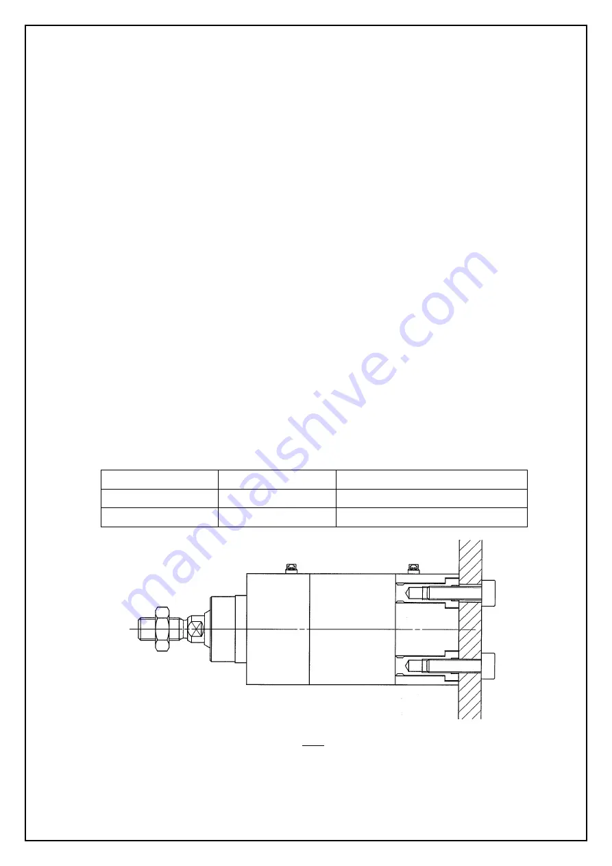
9)  Mount  the  cylinder,  support  bracket  and  plug  bolt  with  the  following  specific  tightening 

torque. 

Table 1 

Applicable bore size 

Thread size 

Tightening torque(N・m) 

Φ32・40 

M6×1 

4.22~7.60 

Φ50・63 

M8×1.25 

10.20~18.40 


Fig 2 


10)  The  mounting  screw  and  bracket  for  the  cylinder  might  let  the  dust  collected  in  some 

operating conditions.


- 

10

  - 


Take a measure depending on the operating conditions when mounting. 

Summary of Contents for HYC 32

Page 1: ...RATION MANUAL HYGIENIC DESIGN CYLINDER Series Read this manual thoroughly before mounting and operating Pay special attention to the safety instructions Keep this manual in an easily accessible locati...

Page 2: ...No FSM027 2B...

Page 3: ...ronment Speed adjustment Direction control Cautions Installation setting up and other Auto switch Model selection Allowable kinetic energy Lateral load at rod end Pneumatic circuit Maintenance and Che...

Page 4: ...ns or after analysis and or tests to meet your specific requirements The expected perfomance and safety assurance will be the responsibility of the person who has determined the compatibility of the s...

Page 5: ...ction for possible failure of either of them Also perform periodical check to ensure it works properly Exemption SMC doesn t take any responsibility for the damage resulting from an earthquake fire du...

Page 6: ...e and mounting dimensions Also different from the conventional actuator it is dedicated for machines in food and packaging industries The concept of hygienic design is not a cylinder which is steriliz...

Page 7: ...ke measures to prevent freezing when below 5 since moisture in circuits can freeze and cause damage to seals and lead to malfunctions The allowable operating range for this product is between Without...

Page 8: ...l and other debris from inside the pipe Wrapping of pipe tape When screwing piping or fitting into ports ensure that chips from the pipe threads or sealing material do not get inside the piping Also w...

Page 9: ...en object will lurch at high speed if pressure is applied to one side of the cylinder because of the absence of air pressure inside the cylinder Therefore equipment should be selected and circuits des...

Page 10: ...ual safely equipment Design the system not to allow external force over max output of the cylinder Excessive external force may break the cylinder and lead to human injury and equipment damage Conside...

Page 11: ...o not scratch or dent the sliding portion of the cylinder tube or the piston rod by striking it with an object or squeezing it The tube bore is manufactured under precise tolerances Thus even a slight...

Page 12: ...iping tube content volume 2 Connect speed exhaust controller ASV and quick exhaust valve in the circuit of the cylinder to exhaust the pressure to atmosphere directly 3 Locate the piping port downward...

Page 13: ...tion for detection at stroke end and Operating Range Table 2 Unit mm Applicable bore size A B Operating Range 32 7 5 16 5 40 12 23 50 9 19 63 19 24 7 5 Fig 3 How to mount auto switch Insert the rail i...

Page 14: ...Minimum Strokes for Auto Switch Mounting Table 3 No of auto swithes D F6 1 5 2 10 12...

Page 15: ...41 0 45 0 54 0 63 40 0 37 0 41 0 45 0 49 0 53 0 57 0 65 0 73 0 81 0 97 1 13 50 0 63 0 69 0 75 0 82 0 88 0 94 1 07 1 19 1 31 1 56 1 81 2 06 63 0 84 0 90 0 96 1 02 1 08 1 15 1 27 1 40 1 52 1 77 2 02 2 2...

Page 16: ...le lateral load 20 F fB P D 4 2 F F Maximum output MPa fB Allowable maximum load to bushing N fB stroke L L L fR 2 1 1 D Bore size mm P Maximum operating pressure MPa fR Allowable mounted load N Fig 5...

Page 17: ...g speed before using When the cushion needle is rotated clockwise the restriction becomes smaller and the cushion works stronger Do not operate the actuator with the cushion needle fully closed This c...

Page 18: ...Pneumatic circuit The typical circuit for HYC series where air filter regulator solenoid valve and speed controller meter out are used for operation is as follows Fig 6 16...

Page 19: ...e caused Removal of equipment and supply and exhaust of compressed air When the equipment is removed after confirming the prevention for drop or run away of the work the cylinder is taken cut off air...

Page 20: ...wdriver etc from the front of the rod cover and take out Take care not to mark or damage the packing groove of the rod cover Likewise insert the precision screwdriver etc from the front of the head co...

Page 21: ...e injured Fig 10 3 Application of grease Rod packing Piston packing and Cushion packing Fig 11 Fig 12 Fig 13 Apply the grease all around new packing evenly Also add the grease inside the groove Fig 11...

Page 22: ...king Then apply the grease on the packing and bearing evenly Fig 16 Piston packing Make sure not to twist the packing when mounting Cushion packing Fig 17 Note the direction when mounting the packing...

Page 23: ...into the cylinder tube Apply the grease to the part receiving the cylinder tube and insert the rod assembly carefully and slowly so as not to damage the piston packing and gasket Tighten the rod cove...

Page 24: ...l Kit Material FKM Content and qty Cushion packing Piston packing Rod packing Tube gasket Needle scraper Bore size mm Kit no Material NBR Material FKM 32 HYCB32H PS 2 1 1 2 2 40 HYCB40H PS 2 1 1 2 2 5...

Page 25: ...during replacement of the packing and maintenance of the cylinder use the grease package Table 11 Grease package Grease for standard for non food Part no Net GR S 010 10g Table 12 Grease package Grea...

Page 26: ...ter including drain Install air cleaning equipments including air filter in the piping and replace piston packing 3 1 A lack of pneumatic pressure The pressure from factory source is low The setting o...

Page 27: ...A lateral load over the allowable value is applied An abnormal external force is applied Adjust the speed with the speed controller again so that the speed will be decreased to within specifications U...

Page 28: ...etaining ring Steel 2 Nickel plated 8 Magnet holder Aluminum alloy 1 Chromated 23 Cushion needle Stainless steel 2 7 Bushing holder Aluminum alloy 1 Chromated 22 Cushion adjuster Stainless steel 2 6 B...

Reviews: