HRX-OM-O021
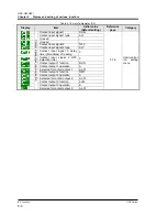
Chapter 5 Display and setting of various functions
HRS Series
5.1
Function
5-3
MENU
Changing of
contact input 1
signal
detection
Alarm
buzzer
sound
Changing of
low tank
level
Changing of
circulating fluid
discharge
temperature rise
Detection
temperature for
circulating fluid
discharge
temperature rise
Changing of
circulating fluid
discharge
temperature drop
Detection
temperature for
circulating fluid
discharge
temperature drop
Changing of
circulating fluid
discharge pressure
rise
Detection pressure
for circulating fluid
discharge pressure
rise
Changing of
communicati
on error
The monitoring
time of
communication
error
PV
SV
PV
SV
PV
SV
PV
SV
PV
SV
PV
SV
PV
SV
PV
SV
Changing of
circulating fluid
discharge pressure
drop
Detection pressure
for circulating fluid
discharge pressure
drop
PV
SV
PV
SV
PV
SV
PV
SV
Changing of
contact input 2
signal
detection
PV
SV
PV
SV
Changing of
DI level rise
Upper limit
of DI level
rise
Changing of
DC line fuse
cut
Changing of
water
leakage
PV
SV
PV
SV
PV
SV
Lower limit
of DI level
drop
Changing of
DI level drop
PV
SV
PV
SV
PV
SV
SEL
SEL
SEL
SEL
SEL
SEL
SEL
SEL
SEL
SEL
SEL
SEL
SEL
SEL
SEL
SEL
SEL
SEL
SEL
Press the
2 sec.
MENU
Alarm setting
menu
MENU
Communicati
on mode
Serial
protocol
Communication
specifications
RS-485
terminal
Slave
address
(
MODBUS
)
Communicati
on
speed
(
MODBUS
)
Slave address
(
Simple
communicatio
n protocol
)
Communication
speed
(
Simple
communication
protocol
)
Response
delay time
(
Simple
communication
protocol
)
Communicati
on
range
(
Simple
communicati
on protocol
)
MENU
BCC
(
Simple
communicatio
n protocol
)
Data length
(
Simple
communicati
on protocol
)
Parity check
(
Simple
communicati
on protocol
)
Stop bit length
(
Simple
communicatio
n protocol
)
Digital input
signal 1
Digital input
signal 1 type
Digital input
signal 2
Digital input
signal 2 type
Digital output
1 function
Digital output
1 operation
Digital output
1 selected
alarm
Digital output
2 function
Digital output
3 selected
alarm
Digital output
2 operation
Digital output
2 selected
alarm
Digital output
3 function
Digital output
3 operation
PV
SV
PV
SV
PV
SV
PV
SV
PV
SV
PV
SV
PV
SV
PV
SV
PV
SV
PV
SV
PV
SV
PV
SV
PV
SV
PV
SV
PV
SV
PV
SV
PV
SV
PV
SV
PV
SV
PV
SV
PV
SV
PV
SV
PV
SV
PV
SV
PV
SV
PV
SV
SV
Press the
2 sec.
Contact input
signal 1 Delay
timer (time
delay) of
reading
Contact input
signal 2 OFF
Detection
timer
PV
SV
PV
SV
Contact input
signal 2
Delay timer
(time delay)
of reading
Contact input
signal 2 OFF
Detection
timer
PV
SV
PV
SV
Communication
setting menu
SEL
SEL
SEL
SEL
SEL
SEL
SEL
SEL
SEL
SEL
SEL
SEL
SEL
SEL
SEL
SEL
SEL
SEL
SEL
SEL
SEL
SEL
SEL
SEL
SEL
SEL
SEL
SEL
SEL
SEL
SEL
PV
Temperature
alarm
Monitoring
method
PV
SV
PV
SV
Monitoring
start timer
PV
SV
Range over
Detection timer
SEL
SEL
SEL
SEL
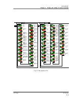
Fig. 5.1-2 Key operation (2/2)


