HRX-OM-L014
1
st
edition: Jun. 2007
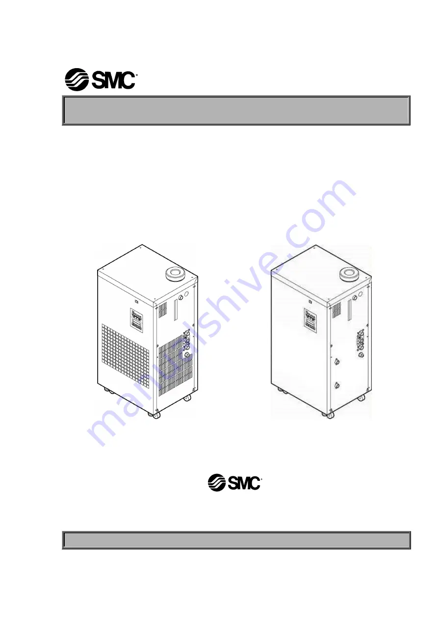
Operation Manual
Refrigerant Type Thermo-cooler
HRGC001-A
∗
∗∗
∗
HRGC001-W
∗
∗∗
∗
HRGC002-A
∗
∗∗
∗
HRGC002-W
∗
∗∗
∗
HRGC005-A
∗
∗∗
∗
HRGC005-W
∗
∗∗
∗
SMC Corporation
Keep this manual available whenever necessary.
© 2007 SMC CORPORATION All Rights Reserved


