


How to Mount and Move the Auto Switch
D-F7K
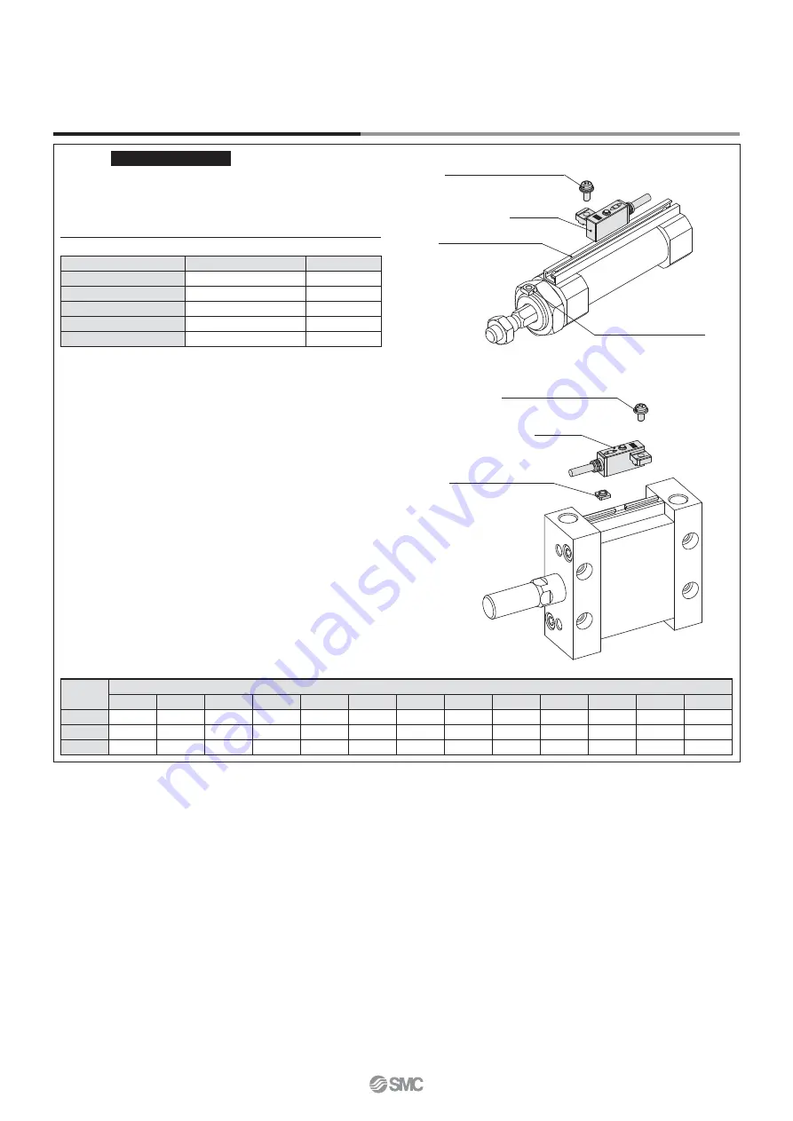
Mounting Bracket
Rail Mounting Type
<Applicable auto switch>
Solid state ······
D-F7K
How to Mount and Move the Auto Switch
1. Slide the auto switch mounting nut inserted into the mounting rail
and set it at the auto switch mounting position.
2. Fit the convex part of auto switch mounting arm into the concave
part of auto switch mounting rail. Then, slide the switch over the
nut.
(Series CDQ2: Fit the convex part of auto switch mounting arm
through the auto switch spacer into the concave part of auto
switch mounting rail.)
3. Push the auto switch mounting screw lightly into the mounting nut
through the hole of auto switch mounting arm.
4. After reconfirming the detecting position, tighten the mounting
screw to secure the auto switch. (Tightening torque of M3 screw
should be 0.5 to 0.7 N·m.)
5. Modification of the detecting position should be made in the
condition of 3.
Auto Switch Mounting Bracket Part No. (Including Nut, Screw, (Spacer))
Cylinder
series
Bore size
12
16
20
25
32
40
50
63
80
100
125
140
160
CQ2
BQ-1
BQ-1
BQ-1
BQ-1
BQ-2
BQ-2
BQ-2
BQ-2
BQ-2
BQ-2
BQ-2
BQ-2
BQ-2
MU
—
—
—
BMU1-025 BMU1-025 BMU1-025 BMU1-025 BMU1-025
—
—
—
—
—
MK/MK2
—
—
BQ-1
BQ-1
BQ-2
BQ-2
BQ-2
BQ-2
—
—
—
—
—
Auto switch
Auto switch mounting rail
Auto switch mounting nut
Auto switch mounting screw
(M3 x 0.5 x 8L)
Auto switch
Auto switch mounting nut
Auto switch mounting screw
(M3 x 0.5 x 6L)
∗
When the CJ2 (rail mounting type) and the CM2-XC13
cylinders are ordered, nuts and screws are included.
Applicable Actuators
Air Cylinders
Description
Series
Bore size
Air cylinder
CJ2
10, 16
Air cylinder
CM2
20 to 40
Compact cylinder
CQ2
12 to 160
Plate cylinder
MU
25 to 63
Rotary clamp cylinder
MK/MK2
20 to 63
6
Trimmer Auto Switch
Series
D-M9K/D-
첸
7K/D-R
첸
K


