HLS300 Power Share Module User Manual
HLS300 Power Share Module Version 1.4 2019-05-16 Page 12 of 14
7
TYPICAL DIAGRAM
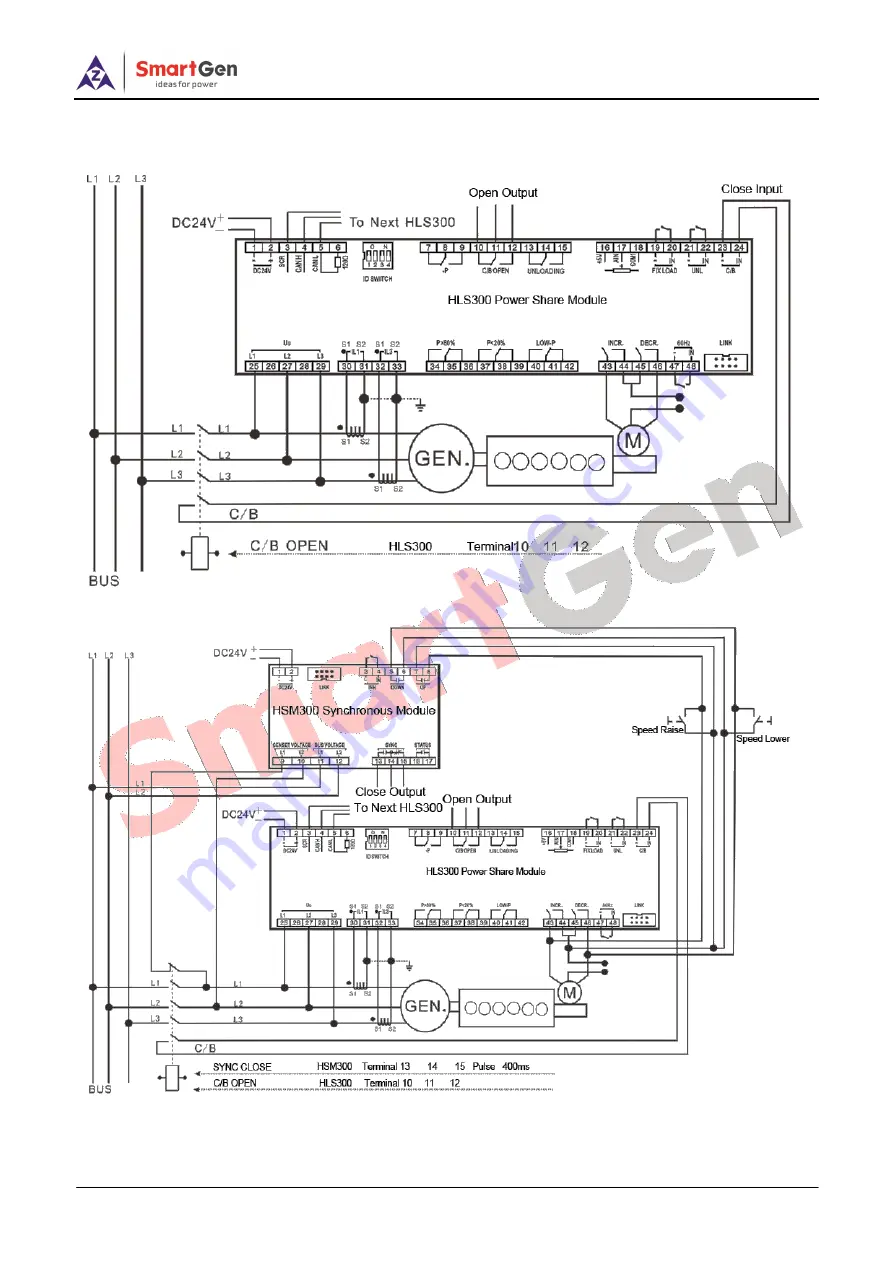
Fig.3 - HLS300 3Phase 3Wire Typical Application
Fig.4 - HSM300-HLS300 3Phase 3Wire Typical Application
Page 1: ...HLS300 POWER SHARE MODULE USER MANUAL SMARTGEN ZHENGZHOU TECHNOLOGY CO LTD ...
Page 2: ...part of this publication should be addressed to SmartGen Technology at the address above Any reference to trademarked product names used within this publication is owned by their respective companies SmartGen Technology reserves the right to change the contents of this document without prior notice Table 1 Software Version Date Version Content 2015 05 21 1 0 Original release 2015 09 07 1 1 Modify ...
Page 3: ...ription Sign Instruction NOTE Highlights an essential element of a procedure to ensure correctness CAUTION Indicates a procedure or practice which if not strictly observed could result in damage or destruction of equipment ...
Page 4: ...ATION 5 4 PANEL INDICATORS AND TERMINALS DESCRIPTION 6 5 SCOPES AND DEFINITIONS OF PROGRAMMABLE PARAMETERS 10 6 FUNCTION DESCRIPTION 11 6 1 INSTRUCTION 11 6 2 FIXED POWER MODE 11 6 3 POWER SHARE MODE 11 6 4 TEST MODE 11 7 TYPICAL DIAGRAM 12 8 CASE DIMENSION 13 9 INSTALLATION PRECAUTIONS 14 9 1 OUTPUT AND EXPAND RELAYS 14 9 2 AC INPUT 14 9 3 WITHSTAND VOLTAGE TEST 14 ...
Page 5: ...puter via SG72 module USB to LINK 8 relay outputs 2 of which are used for controlling INCR speed raise and DECR reduce 5 are used for P UNLOADING P 80 P 20 LOW P output and 1 is used for C B OPEN 1 FIXLOAD mode 1 UNL 1 close and 1 60Hz optional digital input One test button for testing relay output and panel indicators Wide power supply range DC 8 35 V 35mm guide rail mounting Modular design plugg...
Page 6: ... the load is transferring the lamp will illuminate FIXLOAD Green Fixed load mode indicator the lamp will illuminate when input is active UNL Green When Unload is active the lamp will illuminate C B Green When the main switch close is active the lamp will illuminate UG Green When gens is normal the lamp will illuminate when gens is abnormal the lamp will flash when there is not power the lamp will ...
Page 7: ...ery 2 B 1 0mm2 Connected with positive of starter battery 3 SCR 0 5mm2 MSC communication 4 CANH 0 5mm2 5 CANL 0 5mm2 6 Terminal Resistor Match If the terminal resistance match is needed it needs to be short circuited to the terminal 5 or hang in the air 7 Reverse Power Output Normally Close 2 5mm2 Output when reverse power has exceeded set value and the delay is over Normally open N C contactor Vo...
Page 8: ...put when P 80 Pn and delay is over Normally open N C contactor Volts free output 7A Rated 35 COM 36 Normally Close 37 P 20 Output Normally Open 2 5mm2 Output when P 20 Pn and delay is over Normally open N C contactor Volts free output 7A Rated 38 COM 39 Normally Close 40 Low Power Output Normally Open 2 5mm2 Output when P 10 Pn it can be set to P 5 Pn or other value and delay is over Normally open...
Page 9: ... Module Version 1 4 2019 05 16 Page 9 of 14 Fig 2 PC Programming Connection Type NOTE About PC program connection please connect SG72 module Link port with LINK port of this module Through the PC software of our company parameters can be set Please see Fig 2 ...
Page 10: ...75 Threshold 12 70 100 77 Returned 13 0 3600 s 3 Delay 14 Over Freq 0 1 1 0 Disabled 1 Enabled 15 100 120 110 Threshold 16 100 120 104 Returned 17 0 3600 s 3 Delay 18 Under Freq 0 1 1 0 Disabled 1 Enabled 19 80 100 90 Threshold 20 80 100 96 Returned 21 0 3600 s 3 Delay 22 Loss Of Phase 0 1 1 0 Disabled 1 Enabled 23 Phase Rotation Monitor 0 1 1 0 Disabled 1 Enabled 24 CT Ratio 5 5 6000 500 25 Full ...
Page 11: ...onnected with terminal 16 17 18 When close input is active the module will adjust present power to target power and stabilize it between f and P 6 3 POWER SHARE MODE Multiple modules are connected with each other via CAN bus and operate in power share mode together Target power is an average of present power sums of these modules When close input is active the module will adjust present power to t...
Page 12: ...ower Share Module User Manual HLS300 Power Share Module Version 1 4 2019 05 16 Page 12 of 14 7 TYPICAL DIAGRAM Fig 3 HLS300 3Phase 3Wire Typical Application Fig 4 HSM300 HLS300 3Phase 3Wire Typical Application ...
Page 13: ...HLS300 Power Share Module User Manual HLS300 Power Share Module Version 1 4 2019 05 16 Page 13 of 14 Fig 5 HSM300 HLS300 HEP300 3Phase 3Wire Typical Application 8 CASE DIMENSION Fig 6 Overall Dimensions ...
Page 14: ... controller or other equipments 9 2 AC INPUT Current input must be connected to outside current transformer And the current transformer s secondary side current must be 5A Meanwhile the phases of CT and input voltage must be correct otherwise the sampling current and active power may be incorrect NOTE When there is load current transformer s secondary side is prohibitted to have open circuit 9 3 W...