background image

User Manual - twentynine

8.2.7

Matrix Multiplication 3x3

N-by-N matrices are commonly used to transform RGB colors, scale them and control hue, saturation and
contrast. The

CameraSuite SDK

provides a configurable 3-by-3 matrix for various applications, modifying

color images using matrix multiplication operations.

Note

For these operations to be correct, they must be operated on linear brightness values.
If the input image is in a non-linear brightness space, RGB colors must be transformed
into a linear space before these matrix operations are used.

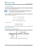
Figure 111 shows how the matrix multiplication is done, where m

x x

are the matrix elements, R

i

/ G

i

/ B

i

are the input original values for the red, green and blue channel and R

o

/ G

o

/ B

o

are the output color

values for the red, green and blue channel.


m

00

m

01

m

02

m

10

m

11

m

12

m

20

m

21

m

22


×


R

i

G

i

B

i


=


R

o

G

o

B

o


Figure 111: Matrix Multi RGB parameters and results

In effect, this calculates:

R

o

=

m

00

·

R

i

+

m

01

·

G

i

+

m

02

·

B

i

G

o

=

m

10

·

R

i

+

m

11

·

G

i

+

m

12

·

B

i

B

o

=

m

20

·

R

i

+

m

21

·

G

i

+

m

22

·

B

i

Common applications for the 3x3 matrix operation are for example color correction, color balancing and the
conversion from color to luminance.

Matrix Multiplication 3x3 in the CameraSuite SDK

In the

CameraSuite SDK

the

ImageProcAPI

provides the programming interface to configure and execute

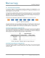
the 3x3 matrix multiplication algorithm. The bit depths and image types supported are shown in Table 59.

Supported bit depth

Supported image input

8 bit per channel

16 bit per channel

Monochrome

X

X

Raw Bayer

X

X

Color RGB

X

X

Table 59: Matrix Multiplication - supported bit depth and image type

134

SMARTEK Vision | User Manual - twentynine | Doc. v1.0.2

Summary of Contents for GCC

Page 1: ...User Manual twentynine Camera Family www SMARTEK vision SMARTEK d o o 2017 information is subject to change without prior notice Version 1 0 2 from 2017 07 03...

Page 2: ...ications These products are not designed for use in life support systems appliances or devices where malfunction of the products can reasonably be expected to result in personal injury Customers Integ...

Page 3: ...pleteness of the information provided SMARTEK d o o shall not be liable of any damages or injury resulting from your reliance on any information provided in this document Copyright All texts pictures...

Page 4: ...2 3 GCC2061 UCC2061 19 2 4 GCC2062 UCC2062 21 2 5 GCC2461 UCC2461 23 2 6 GCC2462 UCC2462 25 3 Physical Interfaces 27 3 1 Gigabit Ethernet Interface GCC 28 3 1 1 Cabling Requirements 28 3 2 USB3 0 Inte...

Page 5: ...2 4 Trigger Activation 61 5 4 2 5 Trigger Delay 62 5 4 3 Free Run Operation 62 5 5 Digital Input Output Control 63 5 5 1 Input Lines 63 5 5 1 1 Line Debouncer 65 5 5 2 Output Lines 66 5 6 GigE Vision...

Page 6: ...witches 101 7 1 3 3 Raising Receive Buffers 102 7 1 3 4 Disable the Interrupt Moderation Rate 103 7 1 3 5 Disable the Flow Control 104 7 2 USB3 Vision 105 7 2 1 Choosing the right USB3 0 Host Controll...

Page 7: ...e supported by one Software Development Kit as well as a large number of 3rd party libraries compliant to the GigE Vision and USB3 Vision standards To use our devices with other software than provided...

Page 8: ...0g Storage temperature 30 C to 60 C Operating housing temperature 0 C to 50 C Operating humidity 20 to 80 relative non condensing Storage humidity 20 to 80 relative non condensing Power requirement 10...

Page 9: ...79 20 1 48 37 50 0 54 13 80 0 60 15 30 2x M 2 0 3x M 3 0 1 14 29 1 14 29 C Mount and image sensor optical center 1 10 27 86 2 12 53 80 1 69 43 0 27 6 80 A Figure 1 Technical measures of the GCC camer...

Page 10: ...0 60 15 30 0 47 12 0 79 20 2x M 2 0 3x M 3 0 1 14 29 1 14 29 C Mount and image sensor optical center 1 10 27 86 2 12 53 80 1 69 43 0 27 6 80 Figure 2 Technical measures of the UCC camera housing all...

Page 11: ...channels on the device It also defines the way for the device to notify an application about specific events GigE Vision Stream Protocol GVSP covers the definition of data types and the ways images an...

Page 12: ...l format gain image offset etc Grabbing images creates access channels between the camera and the user interface and initiates receiving images Graphical user interface enables user GUI interface to s...

Page 13: ...tandard for unified screw threads The flange focal distance is 17 526mm 0 69 and thread length 3 8mm 0 15 1 3 Supported Third Party Software The twentynine cameras have been verified to be applicable...

Page 14: ...are short pass filters that block near infrared light of wavelengths longer than approximately 660nm and pass visible light All color camera models are equipped with an IR cut filter as standard mono...

Page 15: ...t intended to work under wet conditions Do not face this camera towards the sun extremely bright light or light reflecting objects Even when the camera is not in use put the supplied lens cap on the l...

Page 16: ...ach other Avoid coiling camera cables Avoid placing camera cables parallel to wires carrying high current switching voltages such as wires supplying stepper motors or electrical devices that employ sw...

Page 17: ...make sure that the whole surface is constantly in touch Active cooling of the camera by a fan will significantly decrease the temperature Keep the ambience temperature as low as possible Board level c...

Page 18: ...With a small aluminum heat conductor the camera temperature drops about 12 C to 15 C depending on the connection to the heat sink 20 25 30 35 40 45 50 55 0 500 1000 1500 2000 2500 3000 3500 Temperatur...

Page 19: ...e with the essential requirements and other relevant provisions of the following EC directives Reference No Title 2014 30 EU Electromagnetic Compatibility EMC directive Following standards or normativ...

Page 20: ...ent GCC1931C GCC1931M GCC1932C GCC1932M GCC2061C GCC2061M GCC2062C GCC2062M GCC2461C GCC2461M GCC2462C GCC2462M UCC1931C UCC1931M UCC1932C UCC1932M UCC2061C UCC2061M UCC2062C UCC2062M UCC2461C UCC2461...

Page 21: ...size in m 5 86 x 5 86 Analog gain in dB 0 to 24 Shutter Global Shutter Exposure time 26 s to 10s 19 s to 10s Max frame rate in Hz 8Bit 52 164 ADC bit depth 12bit 10bit Pixel data formats mono model M...

Page 22: ...ive Wavelength nm Figure 5 Relative response of GCC1931 UCC1931 Monochrome from sensor datasheet 0 5 0 6 0 7 0 8 0 9 1 0 lative response 0 0 0 1 0 2 0 3 0 4 0 5 400 500 600 700 800 900 1000 Relative W...

Page 23: ...in Hz 8Bit 41 41 ADC bit depth 10bit 10bit Pixel data formats mono model Mono8 Mono12Packed Mono8 Mono10Packed Pixel data formats color model Bayer8 Bayer12Packed Bayer8 Bayer10Packed Synchronization...

Page 24: ...ive Wavelength nm Figure 7 Relative response of GCC1932 UCC1932 Monochrome from sensor datasheet 0 5 0 6 0 7 0 8 0 9 1 0 lative response 0 0 0 1 0 2 0 3 0 4 0 5 400 500 600 700 800 900 1000 Relative W...

Page 25: ...in Hz 8Bit 38 120 ADC bit depth 12bit 10bit Pixel data formats mono model Mono8 Mono12Packed Mono8 Mono10Packed Pixel data formats color model Bayer8 Bayer12Packed Bayer8 Bayer10Packed Synchronization...

Page 26: ...Relative Response Figure 9 Relative response of GCC2061 UCC2061 Monochrome from sensor datasheet Figure 10 Relative response of GCC2061 UCC2061 Color from sensor datasheet 20 SMARTEK Vision User Manua...

Page 27: ...in Hz 8Bit 38 55 ADC bit depth 12bit 12bit Pixel data formats mono model Mono8 Mono12Packed Mono8 Mono10Packed Pixel data formats color model Bayer8 Bayer12Packed Bayer8 Bayer10Packed Synchronization...

Page 28: ...elative Response Figure 11 Relative response of GCC2062 UCC2062 Monochrome from sensor datasheet Figure 12 Relative response of GCC2062 UCC2062 Color from sensor datasheet 22 SMARTEK Vision User Manua...

Page 29: ...in Hz 8Bit 24 75 ADC bit depth 12bit 10bit Pixel data formats mono model Mono8 Mono12Packed Mono8 Mono10Packed Pixel data formats color model Bayer8 Bayer12Packed Bayer8 Bayer10Packed Synchronization...

Page 30: ...elative Response Figure 13 Relative response of GCC2461 UCC2461 Monochrome from sensor datasheet Figure 14 Relative response of GCC2461 UCC2461 Color from sensor datasheet 24 SMARTEK Vision User Manua...

Page 31: ...in Hz 8Bit 24 35 ADC bit depth 12bit 12bit Pixel data formats mono model Mono8 Mono12Packed Mono8 Mono10Packed Pixel data formats color model Bayer8 Bayer12Packed Bayer8 Bayer10Packed Synchronization...

Page 32: ...elative Response Figure 15 Relative response of GCC2462 UCC2462 Monochrome from sensor datasheet Figure 16 Relative response of GCC2462 UCC2462 Color from sensor datasheet 26 SMARTEK Vision User Manua...

Page 33: ...n and GigE Vision cameras Device Vision Standard Interface twentynine GCC GigE Vision Gigabit Ethernet twentynine UCC USB3 Vision USB3 0 Table 10 Data Interfaces of twentynine Series GCC PC GigE NIC E...

Page 34: ...irectional pair B 7 BI_DD Bi directional pair D 8 BI_DD Bi directional pair D Table 11 Ethernet connector type and assignment 3 1 1 Cabling Requirements To connect the camera to a network at least a s...

Page 35: ...rial grade cabling assembled with high grade connectors providing appropiate locking to the camera port The ratio between high frequency characteristics and cooper wire gauge results into a maximum po...

Page 36: ...pin circular Hirose receptacle to provide access to the power interface as well as the input and output lines Figure 20 shows the pin and connector orientation on the back of the camera housing Table...

Page 37: ...ecommended to use a shielded twisted pair cable to avoid EMI the maximum length should not exceed 10m 1 2 3 5 4 6 Figure 21 Hirose 6 pin plug connector Note The 6 pin connector for the cable is a Hiro...

Page 38: ...egion where the transition threshold occurs the logical state is not defined in this region 1 4 to 2 2 VDC Voltage level representing logical 1 2 2 VDC Absolute maximum the camera may be damaged when...

Page 39: ...ically 3 3 VDC Recommended operating voltage 3 3 to 24 VDC Absolute maximum the camera may be damaged if the absolute maximum is exceeded 30 0 VDC The maximum current surge for outputs 25 mA Table 15...

Page 40: ...r of red pulses on the status LED described in Table 16 Status LED Description Steady Green Camera is operational status OK Steady Yellow Camera is powered on and booting up Blinking Red Camera is in...

Page 41: ...ulates in pixels After the integration time has ended accumulated charges are transferred from the light sensitive elements to the Analog Processing block where they are converted to voltages proporti...

Page 42: ...ems in motion scenes due to the fact that the lower lines of the images are later exposed than the top ones Global Shutter sensors show up additional noise and lower sensitivity due to their higher am...

Page 43: ...by filtering off all others and use them to recalculate full color information for each pixel The Bayer color filter array is the most widely used filter array on image sensors which uses the complem...

Page 44: ...ince each pixel accumulates only the intensity value of the red green or blue light there are missing information for displaying a color image At the pixel position of a red color filter for example t...

Page 45: ...nal is received After the Exposure Time the charges of all pixel are simultaneously transferred into protected pixels on the sensor from where they are read out line by line The active array can usual...

Page 46: ...or frame read out tFrameReadout can be calculated by multiplying tReadRow with the total count of lines in the frame tReadRow tReadRow tFrameReadout tFrame tExposure t Line 3 Line 4 Line 5 Line 6 Line...

Page 47: ...me Readout Beyond the illumination period tIllumination ideally no light falls onto the sensor to fully remove the rolling shutter effect The timing of illumination or mechanical shutter can be calcul...

Page 48: ...extended about tReadRow this way to its prior the image lightens up line by line from top to bottom tReadRow tFrameReadout tFrame tExposure t Line 3 Line 4 Line 5 Line 6 Line 7 Line 8 Line N 1 Line N...

Page 49: ...uous Streaming free run Triggered Operation single multi frame Exposure Control Auto Exposure Control 1 1 Frame Rate Control Partial Scan ROI AOI WOI Multiple ROI ROI Centering Binning 2 2 Reverse X H...

Page 50: ...Size in Bytes 8000 Inter Packet Delay Frame Transfer Delay Time Stamps Pixel Data Formats Mono8 1 1 Mono10Packed 1 Mono12Packed 1 Bayer8 3 3 Bayer10Packed 3 Bayer12Packed 3 1 Mono models only 2 Horizo...

Page 51: ...the camera Figure 32 demonstrates two settings of camera s exposure time The picture on the left is captured with an exposure time of 10000 s For the picture on the right the exposure time is set to 2...

Page 52: ...ext of the exposure time a full description of the interface and further supported languages can be found in the API documentation located in the CameraSuite SDK installation folder Note The duration...

Page 53: ...Vision digital cameras gain values are expressed in decibels dB the analog gain defines the ratio between the output and input voltage value in a base 10 logarithmic scale GaindB 20 log10 Uamp Uin Fo...

Page 54: ...odeValue GainSelector double nodeValue Set value of Enumeration node GainSelector bool GetEnumNodeValuesList GainSelector StringList nodeValuesList const Get list of values for Enumeration node GainSe...

Page 55: ...ul signal and needs to be removed before digitizing the signal as it negatively effects the signal to noise ratio To help to remove the dark current component image sensors usually provide an array of...

Page 56: ...Gain algorithm is running continuously Table 23 ExposureAuto and GainAuto operation modes In case when both ExposureAuto and GainAuto are set to Continuous mode the automatic control algorithm always...

Page 57: ...ty of the camera allows to shift the selected bits into the direction of the LSBs As e g by default bits 6 to 13 are used a DigitalShift value of 1 outputs bits 5 to 12 from the ADC Table 25 shows the...

Page 58: ...out the theory of Gamma Correction and or Gamma Adjustment Gamma adjustment is realized by the following formula where y is the new pixel intensity y the original pixel intensity and gamma the gamma v...

Page 59: ...look up table parameters into the client Save Values Save the user defined look up table to a file A common way to set all LUT values at a time in the client is to describe the LUT in a XML file and...

Page 60: ...User Manual twentynine Figure 38 Enable LUT feature on Camera in CameraSuiteClient Figure 39 Modify individual LUT value in CameraSuiteClient 54 SMARTEK Vision User Manual twentynine Doc v1 0 2...

Page 61: ...n Parameter Type Description Width Integer Horizontal size of the ROI image in pixels Height Integer Vertical size of the ROI image in pixels OffsetX Integer Horizontal offset from the origin to the R...

Page 62: ...horizontal and one vertical stripe in the full resolution image as shown in Figure 41 The stripes that are overlapping or are located next to each other are merged into one stripe For example horizont...

Page 63: ...20 288 OffsetX RegionSelector 160 1000 1576 OffsetY RegionSelector 408 232 824 Table 28 Multiple Regions of Interest example When more than one Region of Interest is enabled on the fly changes are not...

Page 64: ...I in the center of the image Parameters OffsetX OffsetY are unavailable when CenterX CenterY are enabled 1 2 3 4 5 6 7 8 9 10 11 12 13 14 15 16 17 18 19 20 1 2 3 4 5 6 7 8 9 10 11 12 13 14 15 16 17 18...

Page 65: ...o acquire for each FrameBurstStart trigger AcquisitionFrameRate Controls the acquisition rate in Hz at which the frames are captured Trigger Features Short description TriggerMode Enable Disable the t...

Page 66: ...Using the AcquisitionFrameRate feature it is possible to decrease the number of frames the camera acquires and transmits in free run mode which consequently lowers the bandwidth required by the camer...

Page 67: ...iggerSource property specifies the internal signal or physical input line to use as the trigger source The selected trigger must have its TriggerMode set to On Possible values for the TriggerSource ar...

Page 68: ...ger reception and before activating it internally A further description of the complete trigger process can be found in 5 5 1 Input Lines 5 4 3 Free Run Operation In Free Run mode the camera starts th...

Page 69: ...r configuration all further properties contain the values based on the selected line Values are Line1 Line2 LineMode Enumeration Specifies if the selected line is an Input or Output LineStatus Boolean...

Page 70: ...User Manual twentynine Figure 45 Partial process of image acquisition 64 SMARTEK Vision User Manual twentynine Doc v1 0 2...

Page 71: ...ause the width of these signals is shorter than the debouncer time value The third signal is accepted as a valid trigger signal as its width is longer than the debouncer time limit The LineDebouncerTi...

Page 72: ...erty AcquisitionTriggerWait High while the camera waits for a trigger for one or more frames AcquisitionActive High while camera acquires one or more frames FrameTriggerWait High while camera waits fo...

Page 73: ...eters settings the driver will then send one or several resend requests to the camera which resends the appropriate packets Table 38 shows the basic driver parameters available Parameter Type Descript...

Page 74: ...ng Integer Maximum time ms that the resend mechanism will wait for the next packet If this time expires and there are still retries left the resend request is sent again MaxMissingPacketsCount Integer...

Page 75: ...is received packet 1007 is detected as missing 3 Interval defined by the PacketResendTimeout parameter 4 The PacketResendTimeout is expired the first resend request for packet 1007 is sent to the came...

Page 76: ...999 1009 1008 1006 1004 1002 1005 1010 1011 1012 1013 1014 Time 3 5 7 1018 1017 1016 1015 1019 1020 4 2 1 8 6 10 9 Figure 48 Packet Resend Mechanism example MaxMissingPacketWaiting value has exceeded...

Page 77: ...low while not using inter packet delay If the Inter Packed Delay is not used excessive collision between packets may occur which results in data loss like illustrated in Figure 49 Packets from two cam...

Page 78: ...twork so time required to transfer one packet of 1538 bytes is 12 3 s The GevSCPD should be a bit longer than the time required to transfer one packet in order to ensure that packets from second camer...

Page 79: ...ffectiveBytesInPacket Payloadsize frame size in bytes retrieved from camera effectiveBytesInPacket number of effective bytes transferred in packet without headers effectiveBytesInPacket GevSCPSPacketS...

Page 80: ...lay needs to be converted from time unit to ticks Before calculating FrameTransferDelay need to be converted to seconds so correct value can be calculated Formula to calculate number of ticks for give...

Page 81: ...ribed by two indices the first index indicates the row while the second index indicates the column where the pixel is located P x y means the pixel located at row x and at column y P 1 1 means the pix...

Page 82: ...an image with the pixel format Mono10Packed each two pixel values are represented by three bytes or 24 bits The Mono10Packed pixel format in SMARTEK Vision digital cameras is specified as shown below...

Page 83: ...icant bit to bit 11 Byte 1 Byte 0 P 1 1 Byte 3 MSB Byte 2 P 1 2 Byte 3 Byte 3 MSB 4 0 3 0 3 11 11 4 Figure 56 Image layout with pixel format Mono12Packed 5 7 5 Mono16 In an image with pixel format Mon...

Page 84: ...formats in SMARTEK Vision digital cameras are specified like shown below PixelFormat BayerGR8 BayerRG8 BayerGB8 BayerBG8 Description 8 bit monochrome unsigned Pixel size 1 byte Value range 0 255 Tabl...

Page 85: ...byte Value range 0 65535 Table 45 Specification PixelFormat Bayer16 The two bytes are arranged in little endian order which means the least significant byte comes first the most significant byte secon...

Page 86: ...c API extends the basic camera functionality provided by the CameraSuite API by color and post processing functions like e g debayering gamma look up table LUT and color correction algorithms Example...

Page 87: ...the installation package the user can choose which part of the SDK to install shown in Figure 60 Figure 60 CameraSuite SDK Setup The installation assistent will guide the user through the installatio...

Page 88: ...ek GigE Vision Filter Driver it can be used with optional flags like v or hide v Optional flag that runs the script with additional information hide Optional flag that runs the script silently Install...

Page 89: ...ation binaries examples docs and drivers 3 TYPE full Full installation binaries examples docs sources and drivers 6 5 CameraSuiteClient The CameraSuiteClient is a Qt based open source application inst...

Page 90: ...selected device Log Display the API log Toolbar Enables quick access to basic functions of the camera find connect disconnect IP setup image handling open save zoom etc GUI handling save GUI arrangem...

Page 91: ...le the user can set his own user interface as default or save it to a file so that his own GUI arrangement can be loaded to the CameraSuiteClient installed on other machines The GUI save and reset fea...

Page 92: ...le flags in front of each camera name displayed in the Devices list Device available and waiting for connection Connection to device established Warning In case the Warning sign is shown in front of a...

Page 93: ...an IP address within the same logical network as the NIC for the camera connection Note If none of the connected cameras was found check the status of the network adapters and their configuration as...

Page 94: ...olor of that field is going to change to yellow shown in Figure 65a With the Permanent is same as Temporary checkbox unchecked it is possible to set a temporary IP address that works for the current s...

Page 95: ...User Manual twentynine Figure 66 Connect Device icon 89 SMARTEK Vision User Manual twentynine Doc v1 0 2...

Page 96: ...shows the parameters of the camera and is only accessible while a connection to the camera is established It displays a tree of features extracted from the GenICam description file of the camera and e...

Page 97: ...eam A running acquisition can be quit by pressing the Stop button Multiple acquisitions can be started in parallel by choosing further cameras the output of the currently selected device is shown in t...

Page 98: ...ties with two connected cameras On the right the Preview dialog contains the video streams of the two cameras This dialog can be enabled through Control Preview in the menu bar The floating displays a...

Page 99: ...of all listed image functions can be found in chapter 8 Image Processing in CameraSuite SDK Tab Functions Comment Color Demosaicing white balancing gamma gain and offset correction AE Auto Exposure Ma...

Page 100: ...to rise or decrease the image buffer within the camera driver which represents space in the non paged memory pool of Windows and can be used to improve the performance when loosing images because of...

Page 101: ...odeActive enable or disable chunk data if chunk data is disabled then normal image is sent ChunkSelector select chunk that will become active ChunkEnable enable or disable active chunk mandatory chunk...

Page 102: ...CounterAndTimerControl Figure 75 Chunk Data Values CounterAndTimerControl Group for counter and timer controls CounterSelector Select which counter will be active CounterEventSource Select source for...

Page 103: ...pplication will run a compatibility test between the device and firmware If the selected firmware is compatible to the selected camera the shown text is tagged as PASSED and the Upload new firmware to...

Page 104: ...ver the PCI Express bus provides guaranteed enough bandwidth for Gigabit Ethernet Jumbo frames reduce the overhead and workload on the target PC reducing the amount of packets to be processed by sendi...

Page 105: ...erface Cards NIC in one PC make absolutely sure that each NIC is configured for a different network Otherwise it will not be possible to operate all cameras correctly 7 1 2 1 IP Setup in Microsoft Win...

Page 106: ...nable the Jumbo Frame Packet feature manually within the device driver On Microsoft Windows operating systems this can be accessed the following way 1 Execute ncpa cpl i e via the command box of the W...

Page 107: ...Packets usually have this feature enabled per default as they offer no way of configuration Professional or so called managed switches which provide a configuration interface in most cases with a web...

Page 108: ...ettings On Microsoft Windows operating systems it can be accessed the following way 1 Execute ncpa cpl i e via the command box of the Windows Startmenu or after pressing R on your keyboard 2 Right cli...

Page 109: ...igure 82 On Microsoft Windows operating systems it can be accessed the following way 1 Execute ncpa cpl i e via the command box of the Windows Startmenu or after pressing R on your keyboard 2 Right cl...

Page 110: ...ed to be disabled On Microsoft Windows operating systems the Flow Control can be accessed the following way 1 Execute ncpa cpl i e via the command box of the Windows Startmenu or after pressing R on y...

Page 111: ...dation To connect the camera to a PC a USB3 0 A to micro B cable is required As USB3 0 is a very compact high speed interface it is highly recommended to only use industrial grade cabling assembled wi...

Page 112: ...essing algorithms Look up Table LUT X X X Digital Gain X X X Auto Exposure X X X White Balance X X Gamma Correction X X X Debayering Demosaicing Bilinear X High Quality Linear X Pixel Grouping X Color...

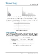
Page 113: ...image 1 The horizontal x axis of the graph 2 contains the intensity values with a range from 0 to 28 1 or 0 to 255 The vertical y axis shows the count of pixels with the corresponding intensity There...

Page 114: ...olor images with the corresponding histograms for each channel Without looking to the images the following information can be determined by the histogram In the first row the population of the pixel v...

Page 115: ...in the CameraSuite SDK In the CameraSuite SDK the ImageProcAPI provides the programming interface to generate histogram data from images The bit depth and image types supported by the histogram featur...

Page 116: ...bled by the menu bar entry Control Histogram shown in Figure 86 Figure 86 Histogram feature in CameraSuiteClient Skip Images default 5 Number of frames to skip before a new histogram is calculated and...

Page 117: ...ation for algorithms like auto exposure and auto white balancing Average Luminance Calculation in the CameraSuite SDK In the CameraSuite SDK the ImageProcAPI provides the programming interface to gene...

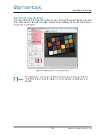
Page 118: ...can be found in the Image Processing Properties under Color Mono shown in Figure 87 If not visible it can be enabled by the menu bar entry Control Image Processing Properties Figure 87 Average value...

Page 119: ...index in the table The corresponding 8 bits output pixel value at index 1 will be 20 When an input pixel value has a value of 3 this value will be used as the index in the table The corresponding 8 bi...

Page 120: ...a variant of gamma correction using a look up table By reference to the look up table and its corresponding graph in Figure 90 it is visible that a non linear transformation is applied to the input p...

Page 121: ...Figure 91 Inverting a monochrome image using look up table The last example demonstrates two implementations of contrast enhancement using a look up table applied to an 8 bit per channel color image...

Page 122: ...le 2 of enhancing contrast of an image using look up table Look up table in CameraSuite SDK In the CameraSuite SDK the ImageProcAPI provides the programming interface for generating and modifying look...

Page 123: ...index 1 value 74 LUT index 2 value 146 LUT index 254 value 250 LUT index 255 value 182 color values xml version 1 0 encoding UTF 8 values color channel Luminance LUT index 0 value 230 LUT index 1 valu...

Page 124: ...ge Processing Properties Figure 95 Look up table feature in CameraSuiteClient Enable LUT Enable application of look up table Reset Reset look up table to default values Load Values Load an user define...

Page 125: ...ially under low light condition Increasing a digital gain value means increasing the intensity of each pixel resulting in a brighter overall image However the image noise will also be increase with di...

Page 126: ...in CameraSuite SDK In the CameraSuite SDK the ImageProcAPI provides the programming interface to apply digital gain to images The bit depths and image types supported are shown in Table 54 For a deta...

Page 127: ...Figure 98 If not visible the panel can be enabled by the menu bar entry Control Image Processing Properties Figure 98 Digital Gain in CameraSuiteClient Note The Digital Gain is used to apply the White...

Page 128: ...igh In this situation the brightness can be further increased applying a digital gain The Auto Exposure feature in the ImageProcAPI provides therefore a property to limit the maximum allowed exposure...

Page 129: ...a 16 bit image 32767 5 2 Min Exposure Time s default 100 minimum exposure time to be calculated This value must not match the minimum exposure time of the image sensor but should not undercut 3 Max Ex...

Page 130: ...The higher the color temperature overcast sky the more blue light will outweigh the digital image appears more bluish To fully describe color casts in digital images a tint adjustment is also require...

Page 131: ...meraSuite API Help located in the doc folder of the CameraSuite SDK installation directory White Balance in the CameraSuiteClient In CameraSuiteClient the user can apply the White Balance algorithm on...

Page 132: ...c Start white balancing calculation once Auto Repeatedly apply white balancing to the images Reset Reset every results calculated by the white balancing process to default If auto white balance is ena...

Page 133: ...For this purpose a well calibrated gray scale is usually used to determine the Gamma Correction values The gamma value can be applied using the ImageProcAPI The term Gamma Correction will be used thro...

Page 134: ...f 0 to 100 Gamma Correction in CameraSuite SDK In the CameraSuite SDK the ImageProcAPI provides the programming interface for setting and executing the gamma correction algorithm The bit depth and ima...

Page 135: ...in and Offset can be accessed in the Image Processing Properties panel under Color Mono shown in Figure 105 If not visible the panel can be enabled by the menu bar entry Control Image Processing Prope...

Page 136: ...nents of light falling onto it Among many CFA patterns the most commonly used is the Bayer pattern For each 2 2 set of pixels two diagonally opposed pixels are equipped with filters which are only tra...

Page 137: ...or interpolation For each pixel its 8 direct neighbors are considered to determine the 2 missing colors of this pixel by simple averaging The red value of a non red pixel is computed as the average of...

Page 138: ...r edge transition In comparison with the bilinear and HQ Linear interpolation methods Pixel Grouping is the most memory and computational intensive algorithm However the result color image is at very...

Page 139: ...der of the CameraSuite SDK installation directory Supported bit depth Supported image input 8 bit per channel 16 bit per channel Monochrome Raw Bayer X X Color RGB Table 58 Demosaicing supported bit d...

Page 140: ...d Ro Go Bo are the output color values for the red green and blue channel m00 m01 m02 m10 m11 m12 m20 m21 m22 Ri Gi Bi Ro Go Bo Figure 111 Matrix Multi RGB parameters and results In effect this calcul...

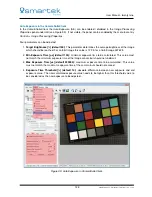
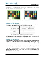
Page 141: ...the panel can be enabled by the menu bar entry Control Image Processing Properties Figure 112 Matrix Multiplication RGB in the CameraSuiteClient Enable Activate deactivate the matrix multiplication fe...

Page 142: ...ng color A more suited color space for manipulating colors is the HSL color space It was developed to interpret colors in a very similar way as humans do wherefore color and brightness information are...

Page 143: ...information the HSL color space fits for various image processing functions such as convolution equalization histograms which mainly use the brightness information for calculation As a result computa...

Page 144: ...try Control Image Processing Properties If Master is selected then values are changed for every channel at once Figure 114 Color GIMP dialog Enable activate deactivate the GIMP Hue Saturation Lightnes...

Page 145: ...voidable Sharpening emphasizes edges and fine details in the image enhancing its visual quality The image seems sharper but no new details are actually created Figure 115 demonstrates the sharpening a...

Page 146: ...h Supported image input 8 bit per channel 16 bit per channel Monochrome X X Raw Bayer Color RGB X X Table 62 Sharpening supported bit depth and image type Sharpening in the CameraSuiteClient In the Ca...

Page 147: ...s Input color image Output grayscale image Figure 117 Example of RGB to gray conversion RGB to Gray Conversion in the CameraSuite SDK In the CameraSuite SDK the ImageProcAPI provides the programming i...

Page 148: ...ray options can be activated in the Image Processing Properties panel under Color shown in Figure 118 If not visible the panel can be enabled by the menu bar entry Control Image Processing Properties...

Page 149: ...ageProcAPI provides the programming interface for converting the bit depth of an image The bit depths and image types supported are shown in Table 64 Supported bit depth Supported image input 8 bit pe...

Page 150: ...cases Figure 119 Example of image flipping Figure 120 Example of image rotation Flipping Rotating in the CameraSuite SDK In the CameraSuite SDK the ImageProcAPI provides the programming interface for...

Page 151: ...ate options can be activated in the Image Processing Properties panel under Color shown in Figure 121 If not visible the panel can be enabled by the menu bar entry Control Image Processing Properties...

Page 152: ...fixed and cannot be modified only the parameters and the execution of each algorithm can be configured For other cases a custom image processing pipeline can by combined by the available algorithms i...

Page 153: ...ine 9 Revision History Ver Chapter Changes Date 1 0 2 All Initial Release Final 2017 07 03 1 0 1 All Initial Release Preliminary 2017 05 19 Table 67 Revision History 147 SMARTEK Vision User Manual twe...

Page 154: ...sarica 5 HR 40000 Cakovec Croatia www SMARTEK vision Email info SMARTEKvision com Tel 385 40 493 805 Fax 385 40 493 819 Copyright 2017 by Smartek d o o All rights reserved For further information plea...

Reviews: