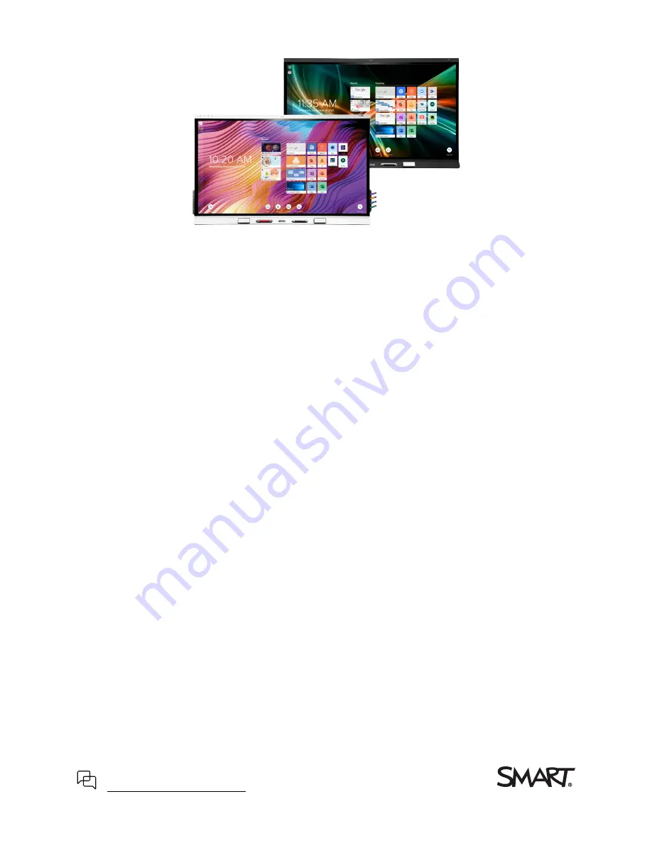
background image

Cover

SMART


Board

®

6000S 

|

 6000S


Pro

series interactive displays

Installation and maintenance guide

SBID-6265S-V3

 | 

SBID-6275S-V3

 | 

SBID-6286S-V3

 | 

SBID-6265S-V3-PW

 | 

SBID-6275S-V3-PW

 | 

SBID-6286S-V3-PW

SBID-6265S-V3-P

 | 

SBID-6275S-V3-P

 | 

SBID-6286S-V3-P

SBID-6065S-V3

 | 

SBID-6075S-V3

 | 

SBID-6086S-V3

 | 

SBID-6065S-V3-PW

 | 

SBID-6075S-V3-PW

 | 

SBID-6086S-V3-PW

SBID-6065S-V3-P

 | 

SBID-6075S-V3-P

 | 

SBID-6086S-V3-P

SBID-6465S-V3-P

 | 

SBID-6475S-V3-P

 | 

SBID-6486S-V3-P

SBID-6265S-C

 | 

SBID-6275S-C

 | 

SBID-6286S-C

 | 

SBID-6265S-CPW

 | 

SBID-6275S-CPW

 | 

SBID-6286S-CPW

SBID-6065S-C

 | 

SBID-6075S-C

 | 

SBID-6086S-C

 | 

SBID-6065S-CPW

 | 

SBID-6075S-CPW

 | 

SBID-6086S-CPW

SBID-6265S

 | 

SBID-6275S

 | 

SBID-6286S

 | 

SBID-6265S-PW

 | 

SBID-6275S-PW

 | 

SBID-6286S-PW

SBID-6065S

 | 

SBID-6075S

 | 

SBID-6086S

 | 

SBID-6065S-PW

 | 

SBID-6075S-PW

 | 

SBID-6086S-PW

IDS665-3

 | 

IDS675-3

 | 

IDS686-3

IDS665-1

 | 

IDS675-1

 | 

IDS686-1

Was this document helpful?

smarttech.com/docfeedback/171414

Summary of Contents for 6000S Pro

Page 1: ...SBID 6065S V3 P SBID 6075S V3 P SBID 6086S V3 P SBID 6465S V3 P SBID 6475S V3 P SBID 6486S V3 P SBID 6265S C SBID 6275S C SBID 6286S C SBID 6265S CPW SBID 6275S CPW SBID 6286S CPW SBID 6065S C SBID 6075S C SBID 6086S C SBID 6065S CPW SBID 6075S CPW SBID 6086S CPW SBID 6265S SBID 6275S SBID 6286S SBID 6265S PW SBID 6275S PW SBID 6286S PW SBID 6065S SBID 6075S SBID 6086S SBID 6065S PW SBID 6075S PW ...

Page 2: ...s or registered trademarks of HDMI Licensing LLC in the United States and other countries The Bluetooth word mark is owned by the Bluetooth SIG Inc and any use of such marks by SMART Technologies ULC is under license Trademark notice SMART Board SMART Notebook SMART TeamWorks SMART Meeting Pro Pen ID HyPr Touch Object Awareness Silktouch Tool Explorer smarttech the SMART logo and all SMART tagline...

Page 3: ...y are properly bundled and marked to avoid a trip hazard l Do not insert objects inside the cabinet ventilation holes because they could touch dangerous voltage points and cause electric shock fire or product damage which may not be covered by the warranty l Do not place heavy objects on the power cable Damage to the cable could cause shock fire or product damage which may not be covered by the wa...

Page 4: ...systems found in some European countries This system IT type is widely used isolated from earth in some installations in France with impedance to earth at 230 400V and in Norway with voltage limiter neutral not distributed at 230V line to line Contact qualified personnel if you re uncertain of the type of power system available where you re installing the display l The accessory slot s maximum ava...

Page 5: ...86S V3 SBID 6X86S V3 PW SBID 6X86S V3 P IDS665 3 100V to 240V AC 50 Hz to 60 Hz 161 W 6000S C and SBID 6000S SBID 6X65S C SBID 6X65S CPW SBID 6X65S SBID 6X65S PW SBID 6X65 P IDS665 1 100V to 240V AC 50 Hz to 60 Hz 92W SBID 6X75S C SBID 6X75S CPW SBID 6X75S SBID 6X75S PW SBID 6075 P IDS675 1 100V to 240V AC 50 Hz to 60 Hz 141W SBID 6X86S C SBID 6X86S CPW SBID 6X85S SBID 6X85S PW SBID 6X86 P IDS686 ...

Page 6: ...g room computers and guest laptops 33 Connecting a SMART OPS PC module 36 Connecting other devices 36 Connector diagrams 40 Chapter 4 Maintaining the display 45 Turning off turning on and resetting the display 45 Cleaning and maintaining hardware 46 Updating system software 50 Chapter 5 Troubleshooting 51 The display isn t turning on 51 The display is turning on when it shouldn t 52 The screen is ...

Page 7: ...mands 80 Volume commands 80 Mute commands 80 Firmware version commands 80 Serial number commands 81 Part number commands 81 Model number commands 81 Resolving issues with managing the display using RS 232 81 Appendix D Managing SMART Board 6000S C or 6000S series displays using RS 232 82 Connecting multiple displays 83 Configuring the computer s serial interface settings 84 Commands and responses ...

Page 8: ...nce panel 13 Proximity sensor 13 Ambient light sensor 14 Remote control and IR sensor 14 Temperature and humidity sensors 15 Microphone array 15 NFC sign in 15 Mounting hardware 15 Accessory mounting points 16 Identifying your specific model 16 Accessories 18 Pen accessory kit 18 Tool Explorer enabled objects and manipulatives 18 SMART OPS PC module 19 Stands 19 USB extenders 19 More information 1...

Page 9: ...on about the display s settings and remote management support This guide is intended for those who install and maintain displays in their organizations Additional documentation and resources are available for users of the display see More information on page 19 About the display The SMART Board 6000S or 6000S Pro series interactive display with iQ is the hub of your classroom or meeting room Note ...

Page 10: ...rovides a natural intuitive writing and touch experience with high accuracy and low latency In addition its Silktouch ultra smooth finish allows you to use the display for hours without finger burn Writing drawing and erasing The display comes with a black pen and a red pen that you can use to write or draw on the screen The display also includes two erasers which you can use to erase digital ink ...

Page 11: ...iQ experience If enabled the display s iQ experience provides one touch access to collaborative tools such as a whiteboard wireless screen sharing and a web browser There s no need for wires cables or manual software and firmware updates Note Some features such as Browser and Screen Share require a properly configured network connection Press the Home button on the display pictured or the remote c...

Page 12: ...n a larger space see Connecting an external audio system on page 38 Network connectivity The display requires a network connection for downloading software and firmware updates and a number of the iQ apps require a network connection as well You can connect to a network using Wi Fi or an Ethernet cable l The Wi Fi module supports both 2 4 and 5 GHz bands l The two RJ45 jacks allow you to connect t...

Page 13: ...eractive displays don t require an iQ appliance in the accessory slot The iQ experience is built into these interactive displays see iQ experience on page 11 For this reason SMART doesn t support installing iQ appliances in these displays accessory slots However the AM50 appliance allows the use of an Intel Compute Card on the 6000S and SMART Board 6000S C models Convenience panel The convenience ...

Page 14: ...his when finding a location for the display see Installing the display on a wall on page 22 Don t position the display so that the sensor is facing a window Ambient light sensor On SMART Board 6000S V3 models the ambient light sensor is located in the top right corner of the display s frame On the 6000S and 6000 C models the sensor is in the top left corner The ambient light sensor detects the roo...

Page 15: ...ophone array while using a conferencing app on the display The microphone array provides improved sound detection You can also use the display s built in microphone array in place of a connected computer s microphone NFC sign in The display allows you to sign in to your SMART Account using NFC near field communication just tap your SMART ID card on the screen and enter a PIN This feature helps you...

Page 16: ...75S V3 White 75 Yes Yes SBID 6286S V3 White 86 Yes Yes SBID 6065S V3 White 65 No Yes SBID 6075S V3 White 75 No Yes SBID 6086S V3 White 86 No Yes 6000 V3 Pro SBID 6265S V3 PW White 65 Yes Yes SBID 6275S V3 PW White 75 Yes Yes SBID 6286S V3 PW White 86 Yes Yes SBID 6065S V3 PW White 65 No Yes SBID 6075S V3 PW White 75 No Yes SBID 6086S V3 PW White 86 No Yes SBID 6265S V3 P Black 65 Yes Yes SBID 6275...

Page 17: ...e 65 Yes No SBID 6275S CPW White 75 Yes No SBID 6286S CPW White 86 Yes No SBID 6065S CPW White 65 No No SBID 6075S CPW White 75 No No SBID 6086S CPW White 86 No No 6000S SBID 6265S White 65 Yes No SBID 6275S White 75 Yes No SBID 6286S White 86 Yes No SBID 6065S White 65 No No SBID 6075S White 75 No No SBID 6086S White 86 No No 6000S Pro SBID 6265S PW White 65 Yes No SBID 6275S PW White 75 Yes No S...

Page 18: ...C module l Stands l USB extenders Note For more information about these and other accessories see smarttech com accessories Pen accessory kit The pen accessory kit includes blue green purple and orange pens and a holder that you can mount on the side of the display Tool Explorer enabled objects and manipulatives The display s Tool Explorer platform enables you to use a range of different pens obje...

Page 19: ...g Note Refer to an application s specifications for information about its computer requirements Stands If you want to move the display from place to place you can install it on a SMART mobile stand If you are installing the display on a wall that cannot support the display s full weight you can install the display on a SMART floor stand USB extenders As noted in the display s specifications there ...

Page 20: ...e stands 27 Using a third party stand 27 Connecting to a network 28 Connecting power and turning on the display for the first time 29 About energy saving modes 30 SMART recommends that only trained installers install the display This chapter is for installers Installers should read this information along with the installation instructions included with the display before they begin the installatio...

Page 21: ...ing to help orient the box during transportation Using transportation aides You can use the following aides to move the display l Cart l Furniture dolly l Mechanical lift Accommodating doorways hallways and elevators In some situations you might need to remove the display from its packaging to move it through narrow doorways or hallways or onto an elevator In these situations keep the foam pieces ...

Page 22: ...r If the display s glass shatters carefully clean up the area and have the display repaired or replaced Warning For safety and to prevent further damage do not continue to install or use the display if its glass is cracked chipped or shattered Saving the original packaging Save the original packaging and repack the display with as much of it as possible if you ever need to move the display after i...

Page 23: ...ere are no nearby heat sources directed at the display such as a radiator or heat vent l There are no nearby shelving units desks or other furniture that has doors or drawers that could hit the display l Furniture wall décor and other room features such as light switches and thermostats do not block the display and are not blocked by it You might be able to move some of these room features to acco...

Page 24: ...kylights and install switches to dim or turn off any lights shining directly on the display s screen Keep in mind that sunlight can come through windows at different angles at different times of the year Acoustics The room has good acoustics see Configuring your SMART Board 6000S for the best audio performance Environment and ventilation l The location meets the environmental requirements in the d...

Page 25: ...ght from the wall to the floor see smarttech com accessories Note Refer to the display s specifications for its weight see More information on page 19 In some situations you may need to request an engineering analysis to determine if the wall can support the display Selecting mounting hardware The mounting hardware required for installation varies according to the type of wall onto which the displ...

Page 26: ...nt the display vertically 90 relative to the floor plus or minus 2 for tolerance and in landscape orientation SMART doesn t support mounting the display at other angles or in portrait orientation l Use M8 bolts included with the wall mount to fasten the bracket Caution Do not over tighten the bolts Use 97 36 177 01 in lb 11 20 N m fasten force l Because the display s receptacles might not be easil...

Page 27: ... Board 6000S C or 6000S series displays using RS 232 on page 82 Installing the display on a stand If you want to move the display from place to place or if it s not possible to install the display on a wall you can install it on a stand Using SMART mobile stands SMART mobile stands are designed for SMART interactive displays They are height adjustable Some models include integrated speakers a lock...

Page 28: ... 6000S C Tip If you re using one of the display s RJ45 jacks to connect to a network you can connect a computer to the other RJ45 jack to provide network access for the computer pictured This is particularly useful if there is only one wired network connection in the room Network access is available when Networked Standby is enabled in Settings but not when Standby is enabled in Settings SMART Boa...

Page 29: ... the display to a power outlet Notes o Refer to the display s specifications for power requirements and power consumption information see More information on page 19 o The AC power output on the back of the display is rated at 250 W To turn on and set up the display for the first time Important Install the OPS PC module before you turn the display on Note If a USB drive is connected to the display...

Page 30: ...g and installing important updates see Updating system software manually on page 50 10 Select the apps you want to appear in the Apps Library and then tap Next Tip To change which apps appear in the Apps Library see Launcher on page 61 11 Tap Finish The Welcome screen appears About energy saving modes The display features a number of energy saving modes l Networked standby a low power state in whi...

Page 31: ...Connecting an external audio system 38 Connecting room control systems 39 Connector diagrams 40 SMART Board 6000S V3 connector panel 40 SMART Board 6000S C and 6000S connector panel 42 Convenience panel 43 Warning Ensure that any cables that cross the floor to the display are properly bundled and marked to avoid a trip hazard Installing SMART software The display comes with the following software ...

Page 32: ...nd any other open window Included with SMART Learning Suite SMART TeamWorks and SMART Meeting Pro software SMART Remote Management Cloud based mobile device management software for remotely maintaining supporting controlling and securing the display and your other devices N A Tip You can purchase additional licenses or subscriptions to SMART software to install on other computers Contact your auth...

Page 33: ...puters and guest laptops By installing cables in advance you make use of connectors that might not be accessible after the display is mounted on the wall You can then run the cables across floors or behind walls as needed Connector panel SMART Board 6000S V3 SMART Board 6000S and 6000S C Convenience panel SMART Board 6000S C and 6000S V3 SMART Board 6000S ...

Page 34: ...Do one of the following If iQ is enabled If iQ is disabled Tap Input on the Home screen OR Press Input on the remote control Press the Home button or the Input button on the remote control The display shows thumbnails of the devices that are connected to the display o A grey thumbnail indicates no device is connected to an input o A black thumbnail indicates a device is connected to an input but i...

Page 35: ... connectors fully populated and wired Stereo 3 5 mm 20 6 m N A USB 2 0 16 5 m Use a USB extender if the distance between the computer and the display is greater than 16 5 m For more information see USB extenders on page 19 USB 2 0 cables support Hi Speed 480 Mbps whether connected to a USB 2 0 or USB 3 0 receptacle For SuperSpeed 5 Gbps connect a USB 3 0 cable to a USB 3 0 receptacle USB 3 0 9 3 m...

Page 36: ...ected to the display using the display s USB plugs For more information see Connecting USB drives peripherals and other devices on the next page Troubleshooting connected computers For troubleshooting information for connected computers see Chapter 5 Troubleshooting on page 51 Connecting a SMART OPS PC module If your organization has purchased a SMART OPS PC module you or your organization s insta...

Page 37: ...l All models include one USB 3 0 Type A receptacle on the connector panel You can connect USB drives peripherals such as keyboards and other devices to these connectors and use the devices with the iQ experience connected computers and devices installed in the accessory slot such as the SMART OPS PC SMART Board 6000S V3 SMART Board 6000S C SMART Board 6000S Connecting an external display You can c...

Page 38: ...nect an external audio system if you re providing sound in a larger space You can connect an external audio system to the display using the stereo 3 5 mm out connector pictured This disables the display s internal speakers Alternatively you can connect an external audio system directly to a room computer SMART Board 6000S V3 SMART Board 6000S and 6000S C In addition to the stereo 3 5 mm out connec...

Page 39: ...volume output Adjusting the display s volume for its internal speakers does not affect the volume output of the S PDIF port Connecting room control systems A room control system enables users to control a room s lighting audio system and possibly the display Some installations may require you to integrate the display with a room control system You can use the display s RS 232 connector to connect ...

Page 40: ...rted USB drives peripherals and other devices See Connecting USB drives peripherals and other devices on page 37 and USB cables and connectors 4 USB 2 0 Type A N A This connector is a service port 1 5 HDMI 2 0 in HDMI 1 input video and audio See page 33 and HDMI cables and connectors 6 USB 3 0 Type B HDMI 1 input touch See page 33 and USB cables and connectors 7 HDMI 2 0 in HDMI 2 input video and ...

Page 41: ... 3 5 mm out External audio system See page 38 and Analog audio cables and connectors 13 RS 232 Room control system See Appendix C Managing the SMART Board 6000S V3 display using RS 232 on page 74 and RS 232 cables and connectors 14 Stereo 3 5 mm in VGA input audio See page 33 and Analog audio cables and connectors 15 USB 3 0 Type B Touch input See page 33 and USB cables and connectors 16 VGA VGA i...

Page 42: ... Supported USB drives peripherals and other devices See Connecting USB drives peripherals and other devices on page 37 and USB cables and connectors 4 USB 3 0 Type B HDMI 1 input touch See page 33 and USB cables and connectors 5 HDMI 2 0 in HDMI 1 input video and audio See page 33 and HDMI cables and connectors 6 USB 3 0 Type B HDMI 2 input touch See page 33 and USB cables and connectors 7 HDMI 2 ...

Page 43: ...cables and connectors 13 USB 3 0 Type B VGA input touch See page 33 and USB cables and connectors Convenience panel The following diagram and table present the connectors on the display s convenience panel No Connector Connects to Notes 1 USB 3 0 Type A3 Supported USB drives peripherals and other devices See Connecting USB drives peripherals and other devices on page 37 and USB cables and connecto...

Page 44: ...DMI 3 input touch See page 33 and USB cables and connectors 3 USB 3 0 Type B HDMI 3 input touch See page 33 and USB cables and connectors 4 HDMI 2 0 in HDMI 3 input video and audio See page 33 and HDMI cables and connectors 5 USB Type C4 USB C See page 33 and HDMI cables and connectors 4SMART Board 6000S C and 6000S V3 models ...

Page 45: ...0 Updating system software manually 50 With proper maintenance the display will provide years of use Turning off turning on and resetting the display In most situations you can put the display in an energy saving mode when not using it following the instructions in the SMART Board 6000S and 6000S Pro series interactive displays user guide smarttech com kb 171415 In some situations such as when you...

Page 46: ...ts Cleaning and maintaining hardware Checking the display installation Inspect the display installation frequently to ensure that the display remains securely installed l Check the mounting location for signs of damage or weakness that can occur over time l Check for loose screws gaps distortions or other issues that could occur with the mounting hardware If you find an issue contact a trained ins...

Page 47: ...Dust buildup on the protective plastic can impair touch performance Inspect these areas for dust and clean them every week Caution l Do not use compressed air to clean the sensors or borders l Do not use water or cleaning agents to clean the touch sensors l Do not apply too much pressure when cleaning the display because you can damage the plastic To clean the IR transmitters and sensors 1 With a ...

Page 48: ...om the wall For more information on removing the display see Removing and transporting the display on the next page Caution Avoid setting up or using the display in an area with excessive levels of dust humidity or smoke Preventing condensation If the display has been moved from a cold environment to a warmer one for example from storage to the installation site let the display sit for a few hours...

Page 49: ...roduct damage Important Follow the documentation included with any third party mounting hardware To remove the display 1 Turn off any connected computers 2 Turn off the display see Turning off turning on and resetting the display on page 45 3 Flick the switch beside the AC power inlet to the OFF O position 4 Remove all accessible cables and connectors 5 Remove any modules from the accessory slot 6...

Page 50: ... s network to allow or prevent automatic system software and firmware updates see Connecting to a network Applying an automatic system software update manually If the display has downloaded the system software update but hasn t yet applied the update you can start the update process manually from Settings To apply an automatic system software update manually 1 From the Home screen tap Settings 2 S...

Page 51: ...ommunity smarttech com s topic 0TOU0000000kAJ0OAM interactive displays tabset 823c7 2 The display isn t turning on Symptom Troubleshooting steps The power light isn t lit l Make sure the power cable is securely fastened to the power outlet and the display Note If the power cable is connected to a power bar make sure the power bar is securely fastened to the power outlet and turned on l Make sure t...

Page 52: ...ng steps The screen is blank l Make sure the screen is working by tapping the Home button below the screen or pressing the Home button on the remote control to open the Home screen l Make sure the display is not in Standby mode by pressing the Power button l Make sure any connected computers are on and not in an energy saving mode l Restart the display and any connected computers See Turning off t...

Page 53: ...e button on the remote control to open the Home screen If it appears correctly the issue is with the video input l Take a photograph of the screen and send it to SMART support If SMART support determines that the issue is with the screen and the display is under warranty you may be eligible for a replacement Colors don t appear correctly l Be aware that if two or more displays are mounted side by ...

Page 54: ...lume on the external audio system and make sure the audio system isn t muted l Adjust the display s audio settings See Audio on page 67 l If you re using the integrated speakers set the volume for the computer and any running applications to 80 and then adjust the display s volume OR If you re using an external audio system set the volume for the computer any running applications and the display t...

Page 55: ...orrect place l Restart the display See Turning off turning on and resetting the display on page 45 l Make sure SMART Product Drivers and SMART Ink are installed and running on any connected computers l Confirm with the installers that the computer is connected to the display with only a single cable l Remove infrared sources such as incandescent or arc lights desk lamps and infrared audio devices ...

Page 56: ...ivers and SMART Ink are installed and running on any connected computers l Use a known working pen from another display to check if the issue is being caused by the pen l Remove infrared sources such as incandescent or arc lights desk lamps and infrared audio devices or move the display to another location in the room l Update the firmware You change the width or color of a pen s digital ink but t...

Page 57: ... as expected See Troubleshooting SMART Product Drivers The SMART OPS PC module isn t working as expected Symptom Troubleshooting steps The SMART OPS PC module isn t working as expected See the SMART OPS PC modules user guide smarttech com kb 171747 Contacting your reseller for additional support If an issue you re experiencing with the display persists or isn t covered in this chapter or the knowl...

Page 58: ...0S Pro series interactive display support pages on the SMART website l The label features the display s base model number for example SBID 6065 V3 Please note this number is different from the actual model SKU number for example SBID 6265 V3 l You can also find the serial number in the iQ settings see Serial Number on page 72 ...

Page 59: ... signed in to your SMART Account Sign out of your SMART Account on the display to see all settings Network settings Option Values Function Notes User or system setting Wi Fi Wi Fi On Off Enables or disables Wi Fi on the display Turn on Wi Fi to discover networks System Wi Fi network name N A Shows information about the connected wireless network N A System Wi Fi MAC address N A Shows MAC address f...

Page 60: ...ess N A Shows information about the network the display is connected to N A System Bluetooth Bluetooth On Off Enable or disable the display s Bluetooth Turn on Bluetooth to view available Bluetooth devices System View available bluetooth devices N A Shows available Bluetooth devices Turn on Bluetooth to view available Bluetooth devices System SMART Cloud Service Region N A Shows the service region...

Page 61: ...ok and Lumio files to the iQ experience User Files Storage N A N A These options are not available for SMART Board 6000S V3 User Allow Google Drive integration in Files Library On Off Enables or disables access to Google Drive when you re signed in to your SMART Account See Opening your Google Drive or OneDrive on the display User Allow OneDrive integration in Files Library On Off Enables or disab...

Page 62: ...ble Finger Inking On Off When enabled you can write with your finger Default is off N A User Enabled Shared Whiteboard On Off When enabled you can share the whiteboard with student devices N A User Screen Share These options are not available for SMART Board 6000S V3 or MX V3 models Require Permission On Off Enables or disables automatic connection from a device sharing its screen N A System AirPl...

Page 63: ...estart Screen Share as a troubleshooting step if a mobile device or computer can t find or connect to the display System Use Web Player On Off When enabled the display uses a different method to stream videos If this method doesn t work disable it to return to the original method System Notifications Do not disturb On Off When enabled the display doesn t show notifications for any app N A System A...

Page 64: ...lliseconds 180 milliseconds 280 milliseconds 560 milliseconds 1120 milliseconds 2080 milliseconds Sets the sensitivity of the Home button Default is 80 milliseconds System Home Button Mode Use physical button to go home Default Sets the behavior of the Home button Default is Low This option is not available for SMART Board 6000S V3 models System Power Turn on when people are nearby On Off Sets the...

Page 65: ... For information about the display s energy saving modes see About energy saving modes on page 30 System Networked Standby Sleep N A If selected the display wakes up faster and can be turned on up by a Wake on LAN command from the network This option is less energy efficient This option is the default for displays not in the EU For information about the display s energy saving modes see About ener...

Page 66: ...e for SMART Board 6000S V3 models System Saturation 0 511 Sets the overall saturation of the image N A This option is not available for SMART Board 6000S V3 models System Red 0 448 Sets the overall red of the image N A System Green 0 448 Sets the overall green of the image N A System Blue 0 448 Sets the overall blue of the image N A System HDMI Output Default resolution Auto 4K60 1080p60 720p60 64...

Page 67: ...lable for SMART Board 6000S V3 models only Volume Range slider Sets the microphone s volume N A System Built in microphone On Off Enables or disables the display s built in microphone The default is on N A System Noise suppression On Off Enables or disables the noise suppression filter for the display s built in microphone The default is on Enable the noise suppression filter to reduce background ...

Page 68: ...twork to allow Network Time Protocol NTP requests to internet time servers See Connecting to a network System Date N A Sets the display s date Disable Automatic date time to set the date manually System Time N A Sets the display s time Disable Automatic date time to set the time manually System 24 Hour Time On Off Shows the display s time using the 24 hour clock N A User Time Zone N A Sets the dis...

Page 69: ...t ID N A Logging Service Languages Sets the language for the settings menu N A User Enable Logging Service On Off Enables or disables saving logs to a USB drive This option allows the temporary iQ system log files to survive a system restart at the cost of some device storage space System Log Levels N A N A N A N A Log Level RAW On Off Advanced logging options to be set under the direction of SMAR...

Page 70: ... A View installed security certificates N A System View root CA certificates N A N A N A System Automatic inactivity log out Disabled 1 hour 8 hours 12 hours Automatically logs a user off after a time of inactivity N A System Enable automatic login On Off Automatically logs in a user if enabled Default is off System Clean up Clean Up Policy Disabled Manually reset with the Clean Up button in the l...

Page 71: ...oftware If an update is available the text changes to Apply update now The display must be connected to the internet to check for system software updates or a USB drive with the system software update file is connected to the display N A Remote Management Launch Remote Management Settings N A Configure the display s connection settings with the Radix Viso server This option is only enabled when Re...

Page 72: ...nterprise iQ experience ENT NoiQ Enterprise display only configuration without iQ Shows the display s iQ system configuration N A N A Firmware Details N A N A N A N A Touch controller firmware version N A Shows the display s touch controller firmware version N A N A Scaler version N A Shows the display s scaler version This option is not available for the SMART Board 6000S V3 6000S C and 6000S mod...

Page 73: ...splay with your organization s SMART Remote Management account When you enroll one of these displays you can use SMART Remote Management to centrally control features and settings for the display such as l blocklists and allowlists l Wi Fi l wallpaper l certificates l lock screen l available apps To learn how to enroll your display see Enrolling a SMART Board interactive display in SMART Remote Ma...

Page 74: ...n shade commands 80 Volume commands 80 Mute commands 80 Firmware version commands 80 Serial number commands 81 Part number commands 81 Model number commands 81 Resolving issues with managing the display using RS 232 81 You can connect an RS 232 cable from a computer s serial output to the display s RS 232 in connector to remotely select video inputs turn the display on or off and get information a...

Page 75: ...onfiguring the computer s serial interface settings Configure the computer s serial interface before sending commands to the display To configure the computer s serial interface 1 Turn on the display 2 Turn on the computer and then start the serial communications program or terminal emulation program 3 Activate local echo 4 Configure the serial interface settings using the following values and the...

Page 76: ...atted commands l Commands aren t case sensitive and extra spacing is ignored l In many terminal applications on a computer you can use the BACKSPACE key when typing commands l Review each entry carefully before sending a command to the display l Don t send another command until you receive the response and the next command prompt If no command prompt is present send a carriage return character CR ...

Page 77: ...mber This example increases the volume by 5 set volume 5 volume 70 This example decreases the volume by 15 set volume 15 volume 55 Power state commands Get command Set command Response get powerstate set powerstate Value Where Value is one of the following l on l ready l standby l powersave Note If the display is in UPDATEON or UPDATEREADY state it might not change power states after receiving the...

Page 78: ... in the room l A user presses the Power button on the convenience panel or the remote control l The display receives set powerstate ready or set powerstate on command This power state is the default energy saving mode for displays set to a non EU location Note The EU uses networked standby to describe this power state POWERSAVE The screen is off and the display is a very low power state The displa...

Page 79: ...i2 l hdmi3 l vga1 l ops1 l usbc1 l usbc2 l android input Value Where Value is one of the following l hdmi1 l hdmi2 l hdmi3 l vga1 l ops1 l usbc1 l usbc2 l android l none Brightness commands Get command Set command Response get brightness set brightness Value Where Value is one of the following l Value l Value l 0 100 brightness Value Where Value is a number between 0 and 100 Freeze commands Get co...

Page 80: ...me set volume Value Where Value is one of the following l Value l Value l 0 100 Note l If the display s audio is muted changing the volume also un mutes the audio l Setting the volume to zero also mutes the volume volume Value Where Value is a number between 0 and 100 Mute commands Get command Set command Response get mute set mute Value Where Value is one of the following l on l off mute Value Wh...

Page 81: ...ng RS 232 The following table presents common issues with managing the display using RS 232 and explains how to resolve them Symptom Troubleshooting steps Managing the display using RS 232 isn t working as expected l Make sure all the cable connections are secure l Restart the display and the remote management system See Turning off turning on and resetting the display on page 45 l Configure the s...

Page 82: ...mmands 89 Freeze commands 89 Screen shade commands 90 Volume commands 90 Mute commands 90 Firmware version commands 90 Serial number commands 91 Part number commands 91 Resolving issues with managing the display using RS 232 91 You can connect an RS 232 cable from a computer s serial output to the display s RS 232 in connector to remotely select video inputs turn the display on or off and get info...

Page 83: ...ultiple displays You can connect up to ten displays to a room control system by connecting a RS 232 cable from the computer s serial output to the first display s RS 232 in connector and then connecting another RS 232 cable from that display s RS 232 out connector to the next display s RS 232 in connector Notes l The leftmost display when viewed from the front is the first display in the chain the...

Page 84: ... interface settings using the following values and then press ENTER Baud rate 19200 Data length 8 Parity bit None Stop bit 1 A command prompt appears on the following line and the display can now accept commands from the computer Note If no message appears or an error message appears the serial interface isn t configured correctly Repeat steps 3 and 4 Commands and responses To access display infor...

Page 85: ...fully before sending a command to the display l Don t send another command until you receive the response and the next command prompt If no command prompt is present send a carriage return character CR to the display If the display is ready to receive commands it will show a command prompt after receiving the carriage return To retrieve a setting s current value Use a get command This example show...

Page 86: ...xample decreases the volume by 15 set volume 15 volume 55 To identify or assign a value for a specific display Start the command with Display where Display is the display you want to apply the command to This example sets the input for the first display in the chain to HDMI 2 A set input hdmi2 A input hdmi2 Notes o The first display in the chain is labeled A the next display is labeled B and so on...

Page 87: ...en is off but the display is ready to turn on when one of the following occurs l A user presses the Power button on the convenience panel or the remote control l A user picks up a pen or the eraser l You send the set powerstate on command l The proximity sensors detect people in the room l The display receives a video signal STANDBY The screen is off and the display is in a low power state The dis...

Page 88: ...dby to describe this power state UPDATEON The display is updating firmware Do not turn off the display UPDATEREADY The display is updating firmware while the screen is off Do not turn off the display With the exception of get powerstate and set powerstate commands are available only when the display is in READY or ON power state Input commands Get command Set command Response If one display is con...

Page 89: ...o ops1 o android Display input Value Where l Display is the display s label A B and so on l Value is one of the following o hdmi1 o hdmi2 o hdmi3 o vga1 o ops1 o android o none Brightness commands Get command Set command Response get brightness set brightness Value Where Value is one of the following l Value l Value l 5 100 brightness Value Where Value is a number between 5 and 100 Freeze commands...

Page 90: ...wing l Value l Value l 0 100 volume Value Where Value is a number between 0 and 100 Mute commands Get command Set command Response get mute set mute Value Where Value is one of the following l on l off mute Value Where Value is one of the following l on l off Firmware version commands Get command Response If one display is connected get fwversion fwversion Value Where Value is the firmware version...

Page 91: ...parated by commas Resolving issues with managing the display using RS 232 The following table presents common issues with managing the display using RS 232 and explains how to resolve them Symptom Troubleshooting steps Managing the display using RS 232 isn t working as expected l Make sure all the cable connections are secure l Restart the display and the remote management system See Turning off t...

Page 92: ...hrough 13 Radiation exposure statement This equipment complies with FCC radiation exposure limits set forth for an uncontrolled environment This equipment should be installed and operated with minimum distance of 20 cm between the antenna of this device and all nearby persons This transmitter must not be co located or operated in conjunction with any other antenna or transmitter Innovation Science...

Page 93: ...it pas être co implantés ou exploités conjointement avec une autre antenne ou émetteur EU Declaration of Conformity Hereby SMART Technologies ULC declares that the radio equipment type Interactive Display IDS665 3 IDS675 3 IDS686 3 IDS665 1 IDS675 1 IDS686 1 and the OPS AM50 PCM8 are in compliance with Directive 2014 53 EU The full text of the EU declaration of conformity is available at the follo...

Page 94: ...nufactured sold and disposed of in a safe and environmentally friendly manner Waste Electrical and Electronic Equipment WEEE Electrical and electronic equipment and batteries contain substances that can be harmful to the environment and to human health The crossed out wheeled bin symbol indicates that products should be disposed of in the appropriate recycling stream and not as regular waste Batte...

Page 95: ...smarttech com kb 171414 SMART Technologies smarttech com support smarttech com contactsupport ...

Reviews: