LEARN
P/B
MODE
MENU
SET
M1
M2
LEARN
P/B
MODE
MENU
SET
M1
M2
HALL
GND
GND
+5V
(H2)
(–)
(–)
(+)
HALL
GND
GND
+5V
(H2)
(–)
(–)
(+)
-8-
Electrical Connection
WARNING
Do not fix the control box or junction box
upside down. This will cause water and/or condensation
to enter through the cable glands and will void the
warranty.
Motor Connection for Single Leaf Gate
For single leaf gate the opener is prewired ready for set
up. Simply connect the motor connector cable from the
controller to the motor.
Go to page 11 to code transmitters then page 11 for limits
set up procedure.
Motor Connection for Two Leaf Gate
For a two leaf gate a junction box is required with
connection via a 5-core cable or 2-core for motor power
plus
RJ45 positioning encoder cable (supplied in your
kit). Ensure that the cable is properly protected with a
cable gland at each end and a suitable conduit across or
under the driveway.
Note:
Motor 1 is the primary opener and opens first. The
leaf that has the trailing edge/overlap is opened by
motor 2. If you need to swap the motors over so
that the overlap is on the same side as the control
box swap the motor and encoder wires over.
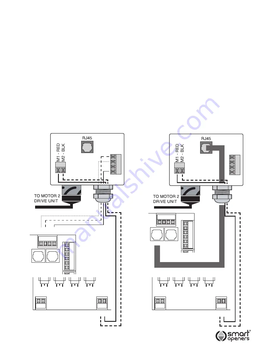
Connect 5-core cable from Motor 2 and encoder
terminals in the control box to the Motor 2 Junction Box
as per wiring diagram (Fig. 5).
Alternatively use an RJ45 cable for the encoder
connection as per Fig. 6.
Fig. 5
Fig. 6
LEARN
P/B
MODE
MENU
SET
LEARN
P/B
MODE
MENU
SET
Com
Push Btn
Ped
Stop
Close
Open
Com
Push Btn
Ped
Stop
Close
Open
MOT
OR 2
JUNCTION BOX
MOT
OR 2
JUNCTION BOX
MOTOR CONNECTION
WITH 5-CORE CABLE
MOTOR CONNECTION
WITH RJ45 CABLE
2 1
BLACK
BLACK
RED
RED
2 1
2 1
2 1
- H2 H1 +
Encoder 2 Encoder 1
Encoder 2 Encoder 1
© November 2011 Smart Openers Pty Ltd


