background image

5  Troubleshooting

SMA Solar Technology AG

Maintenance Manual

SCCPXT-E7-WA-en-37

36

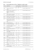
Error no. Explanation

Inverter behavior

Corrective measures

S1

S2

R

3501

The insulation monitoring device
has measured a too low ground-
ing resistance.

C

C

• Check the PV array for ground faults.

3502

The GFDI has tripped.

C

C

• Check the PV array for ground faults.

3504

The insulation monitoring device
has detected an insulation error.

If the parameter 

IsoErrIgn

 is set to

On

, this error is ignored.

W

W

• Check the PV array for ground faults.

3507

A ground fault has occurred on
the ungrounded terminal of the PV
array.

Q

Q

• Check the PV array for ground faults.

3510

The inverter has detected an insu-
lation error on the inverter bridge.

Q

Q

• Check the PV array for ground faults.

3511

The inverter has detected an insu-
lation error.

W

W

• Check the PV array for ground faults.

3512

The Remote GFDI has detected a
permanent ground fault.

Q

Q

• Check the PV array for ground faults.

3515

A ground fault detected by
Soft Grounding has been ignored.

W

W

• Check the PV array for ground faults.

3517

Insulation measuring is being per-
formed.

W

W

3520

An insulation fault has occurred
and has been fixed.

W

W

3601

Leakage current to ground has oc-
curred in the PV array or the
threshold defined in parameter

RisoCtlWarn

 has been reached.

W

W

• Check the grounding and equipotential

bonding.

• Check the module wiring and system

design.

• Check the parameter 

RisoCtlWarn

.

3803

The PV array current is too high.

1 min

D

• Check the DC input current.

• Check the module wiring and system

design.

4003

Reverse currents detected in the PV
array or DC connection polarity
reversed.

30 s

Q

• Check the PV modules for short circuits.

• Check the module wiring and system

design.

• Check the DC terminals for correct

polarity.

• Check the functionality of the entire

string.

Summary of Contents for SUNNY CENTRAL 1000CP XT

Page 1: ...SCCPXT E7 WA en 37 98 107200 05 Version 3 7 ENGLISH Maintenance Manual SUNNY CENTRAL 500CP XT 630CP XT 720CP XT 760CP XT 800CP XT 850CP XT 900CP XT 1000CP XT...

Page 2: ...under any circumstances The exclusion of implied warranties may not apply in all cases under some statutes and thus the above exclusion may not apply Specifications are subject to change without notic...

Page 3: ...1 Design 17 3 3 2 2 Explanation of Symbols 17 3 3 3 LEDs of the SC COM 21 3 3 3 1 LEDs on the Enclosure 21 3 3 3 2 LEDs on the Network Port 22 3 3 3 3 LEDs on the Optical Fiber Terminals 23 3 3 4 Use...

Page 4: ...24 Months 43 6 3 Repair Schedule and Spare Parts 44 6 3 1 Information on Repair Work 44 6 3 2 Demand Based Annual Repairs 45 6 3 3 Repairs every 10 Years 45 6 3 4 Repairs every 12 Years 45 6 4 Mainte...

Page 5: ...ouch Display 65 7 3 Parameter Overview 65 7 3 1 Accessing the Parameter Overview 65 7 3 2 Saving Parameter Changes 66 7 4 User Interface 66 7 4 1 Logging Into the User Interface 66 7 4 2 Logging Out o...

Page 6: ...eal product 1 2 Target Group The tasks described in this document must only be performed by qualified persons Qualified persons must have the following skills Knowledge of how the product works and is...

Page 7: ...nals Elements on a user interface Elements to be selected Elements to be entered Connect the insulated conductors to the terminals X703 1 to X703 6 Enter 10 in the field Minutes Connects several eleme...

Page 8: ...internal power supply for SUNNY CENTRAL and SUNNY CENTRAL STORAGE Technical Information PUBLIC CYBER SECURITY Guidelines for a Secure PV System Communication Technical information For information on m...

Page 9: ...NY CENTRAL Do not deactivate or modify settings that affect grid management services without first obtaining approval from the grid operator Use this product only in accordance with the information pr...

Page 10: ...arge completely see Section 4 2 page 26 DANGER Danger to life due to electric shock when live components or DC cables are touched When exposed to sunlight the PV modules generate high DC voltage which...

Page 11: ...ltage to ground Entering the PV field can result in lethal electric shocks Ensure that the insulation resistance of the PV field exceeds the minimum value The minimum value of the insulation resistanc...

Page 12: ...TICE Property damage due to dust intrusion and moisture penetration Dust or moisture intrusion can damage the product and impair its functionality Do not open the enclosure during rainfall or when hum...

Page 13: ...e art and are very expensive to use special communication interfaces separate wide area networks and more When using the Internet infrastructure the systems connected to the Internet are entering a ba...

Page 14: ...F C G Figure 2 Inverter Components Position Component Description A Touch Display Different kinds of inverter data can be viewed on the touch display The touch display is only used to view data The d...

Page 15: ...key switch Position Designation A Switch position Stop B Switch position Start Switch position Start If the key switch is turned to Start a motor drive switches the DC switchgear on and the inverter s...

Page 16: ...Position Designation Explanation A Switch position on The AC disconnection unit is closed B Central switch position The AC disconnection unit was tripped and is open C Switch position off The AC disc...

Page 17: ...lock the display again The touch display is divided into three areas 100 DD MM YYYY hh mm ss A B C Figure 6 Design of the touch display Position Designation Explanation A Status info line Number of th...

Page 18: ...Inverter data symbol the DC switchgear is closed If you see this symbol between the symbol Inverter data and the symbol AC side the AC contactor is closed Switch on DC or AC side open If you see this...

Page 19: ...citation type of the displacement power factor Actual reactive power in VAr Actual displacement power factor cos Actual excitation type of the displacement power factor Settings Menu Symbol Designatio...

Page 20: ...ssword entry Information OS version of the operating system App version of the application software SC COM version SC COM software version Ser No inverter serial number Hardware hardware version and s...

Page 21: ...ge SD1 flashing green Read or write access to system drive SD2 flashing green Read or write access to internal data drive CF flashing green Read or write access to external SD memory card H1 flashing...

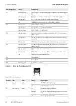
Page 22: ...s used glowing red The internal memory card is full and the oldest saved data is being overwritten flashing red 92 of the storage capacity of the internal memory card is used H5 glowing green An exter...

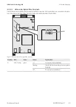
Page 23: ...ions If the optical fibers are connected to the splice box of the inverter the status of the connection will be indicated by the LEDs of the SC COM Figure 9 LEDs for the status of the optical fiber co...

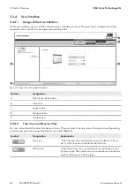
Page 24: ...ice view B Status bar C Logout button D Navigation bar E Content area 3 3 4 2 Tree View and Device View You can call up data of the individual devices of your PV power plant in the tree view or the de...

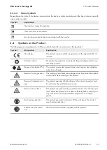
Page 25: ...equipment is connected to the grounding conductor sys tem of the product Degree of protection IP54 The product is protected against interior dust deposits and splashing water from all angles Beware of...

Page 26: ...f burns due to hot components Some components of the product can get very hot during operation Touching these components can cause burns Observe the warnings on all components During operation do not...

Page 27: ...components 4 2 4 Disconnecting the Supply Voltage at the Inverter from Voltage Sources 1 If the supply voltage is only to be disconnected upstream from the circuit breaker switch the circuit breaker...

Page 28: ...Reconnecting the Supply Voltage at the Inverter 1 Close the measurement and disconnect terminals 2 Switch on the motor protective circuit breakers of the grid monitoring 3 Connect any additional exter...

Page 29: ...ee Section 4 3 1 page 28 2 Reconnect the AC voltage of the MV transformer 3 Switch on the AC disconnection unit in the inverter 4 3 3 Reconnecting the DC Side 1 Insert all fuses and disconnection blad...

Page 30: ...njury due to electric shock Disconnect the external supply voltage WARNING Hearing impairment due to high frequency noises of the product The product generates high frequency noises during operation T...

Page 31: ...Downloading the Event Report The event report keeps a log of various events e g errors and warnings All events can be downloaded in a CSV file Upon delivery the automatic transfer of the events is dea...

Page 32: ...waiting time The waiting time specifies how long the disturbance will be shown on the touch display and saved as a disturbance Once the waiting time has elapsed the disturbance is no longer shown on t...

Page 33: ...ether the cause of the disturbance has been rectified If the disturbance is no longer pending it is deleted from the memory If the cause of the disturbance still exists after the disturbance has been...

Page 34: ...When the inverter monitors the utility grid after a grid error the grid monitoring time is complied with Certain errors such as grid errors cause the inverter to shut down In this case the instantaneo...

Page 35: ...and alone grid and has disconnected from the utility grid W W Check power frequency 0801 One line conductor of the utility grid has failed 30 s 30 s Check the grid voltage Make sure the external fuses...

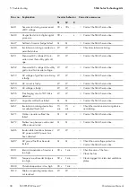
Page 36: ...n error W W Check the PV array for ground faults 3512 The Remote GFDI has detected a permanent ground fault Q Q Check the PV array for ground faults 3515 A ground fault detected by Soft Grounding has...

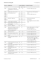
Page 37: ...rvice Line 6121 No response from watchdog 30 s W Contact the SMA Service Line 6122 Ten internal monitoring errors have occurred in succession W 5 min Contact the SMA Service Line 6128 General error 5...

Page 38: ...ct the SMA Service Line 6455 AC voltage is faulty W W Contact the SMA Service Line 6456 Pre charging circuit of DC link is defective W W Contact the SMA Service Line 6457 Capacitor self test has faile...

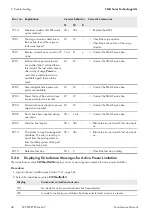
Page 39: ...splay only W W Check cabling between touch display and communication unit Contact the SMA Service Line 7601 Internal inverter error 30 s 1 min x Contact the SMA Service Line 7602 Internal communicatio...

Page 40: ...etpoint is invalid W W Contact the SMA Service Line 8704 External active and reactive power setpoints are invalid W W Contact the SMA Service Line 9008 Doors have been opened during operation 30 s 1 m...

Page 41: ...displays errors or warnings relating to the reactive power setpoint Procedure 1 Log into the user interface see Section 7 4 1 page 66 2 Select the instantaneous value Q VArModFailStt Display Cause and...

Page 42: ...open the enclosure during rainfall or when humidity exceeds the specified thresholds The humidity thresholds are 15 to 95 Only perform maintenance work when the environment is dry and free of dust Op...

Page 43: ...or parts recommended by SMA Solar Technology AG are to be used as spare parts when replacing components Spare parts can be identified via the reference designation and the circuit diagram The spare p...

Page 44: ...e 47 Check the labels Section 6 4 2 11 page 59 Checking the inverter surface Section 6 4 2 8 page 57 Maintenance work with supply voltage present Task See Checking the DC switchgear Manufacturer docum...

Page 45: ...ntact the Service see Section 9 page 68 Replace the fans of the AC disconnection unit Contact the Service see Section 9 page 68 Replace exterior key switch front element and label Contact the Service...

Page 46: ...t to allow the capacitors to discharge completely Disconnect the inverter see Section 4 page 26 CAUTION Risk of burns due to hot components Some components of the product can get very hot during opera...

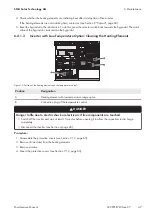
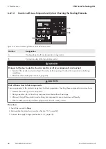
Page 47: ...on Cleaning the Heating Elements Figure 12 Position of the heating elements and the temperature control Position Designation A Heating element with low temperature range option B Connection plug of th...

Page 48: ...ore opening it to allow the capacitors to discharge completely Disconnect the inverter see Section 4 page 26 CAUTION Risk of burns due to hot components Some components of the product can get very hot...

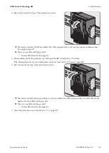
Page 49: ...Technology AG 5 Check whether the heating elements are radiating heat after a delay time of 5 minutes If the heating elements are not radiating heat contact us see Section 9 Contact page 68 6 Insert...

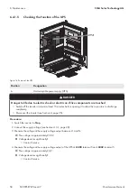
Page 50: ...utes before opening it to allow the capacitors to discharge completely Disconnect the inverter see Section 4 page 26 Procedure 1 Switch the inverter to Stop 2 Connect the supply voltage see Section 4...

Page 51: ...nect the inverter see Section 4 page 26 Procedure 1 Check the inverter for visual defects such as discoloration dirt damage and scratches on the enclosure If visual defects are present repair these im...

Page 52: ...ol Temperature Indicators Analysis Protocol can be downloaded at www SMA Solar com DANGER Danger to life due to electric shock or electric arc if live components are touched Switch off the inverter an...

Page 53: ...6 Procedure 1 Disassemble the panels see Section 7 1 1 page 62 2 Pull the ventilation plate out of the inverter cabinet Grip underneath the ventilation plate and press the middle part up while pulling...

Page 54: ...the inverter via the grounding conductor If the roof is not disassembled correctly the grounding conductors may be pulled out Take care not to damage the grounding conductors during disassembly Proced...

Page 55: ...he inverter and pull forward 10 Press the roof down 11 Mount the ventilation grids see Section 7 1 3 page 64 6 4 2 5 Cleaning the Interior DANGER Danger to life due to electric shock or electric arc i...

Page 56: ...ter and wait at least 15 minutes before opening it to allow the capacitors to discharge completely Disconnect the inverter see Section 4 page 26 Procedure 1 Check whether the seals in the sealing area...

Page 57: ...ck and the key switch in order to protect them from icing up 6 4 2 8 Checking the Inverter Surface Required maintenance material not included in the scope of delivery Abrasive cloth Degreaser Use touc...

Page 58: ...he fuses disconnection blades and tension springs for any discoloration or change in appearance If they are discolored or changed in any way replace them 2 Check insulation and terminals for any disco...

Page 59: ...If bolted connections are loose tighten them using a torque wrench 2 Check whether all bolted connections of the power cabling are securely in place If bolted connections are loose tighten them using...

Page 60: ...B 86 05200 Beware of dangerous voltage C 86 79615 Beware of a danger zone D 86 10867153 Risk of electrical shock even when the device is disconnected 86 003307 5 Safety rules 86 003314 Risk of lethal...

Page 61: ...when the device is disconnected DANGER Danger to life due to electric shock or electric arc if live components are touched Switch off the inverter and wait at least 15 minutes before opening it to all...

Page 62: ...ted to the inverter via the grounding conductor If the roof is not disassembled correctly the grounding conductors may be pulled out Take care not to damage the grounding conductors during disassembly...

Page 63: ...rc if live components are touched Switch off the inverter and wait at least 15 minutes before opening it to allow the capacitors to discharge completely Disconnect the inverter see Section 4 page 26 D...

Page 64: ...ids 1 Release the screws of the right hand ventilation grid head size T40 2 Pull the lower side of the right hand ventilation grid forwards to remove it 3 Release the screws of the left hand ventilati...

Page 65: ...the Password via the Touch Display Installer access The Installer access level is activated by entering the installer password The access level is reset after 15 minutes Procedure 1 Select 2 Select 3...

Page 66: ...for the user groups If your user password is the same as your installer password you will automatically be logged in as an installer Requirement JavaScript must be enabled in your web browser e g Int...

Page 67: ...5 Nm 8 2 Type Label The type label clearly identifies the product One type label is present in the inverter The type label is located in the right hand top corner inside the interface cabinet You wil...

Page 68: ...elgien Belgique Belgi Luxemburg Luxembourg Nederland SMA Benelux BVBA SPRL Mechelen 32 15 286 730 for Netherlands 31 30 2492 000 SMA Online Service Center www SMA Service com esko Magyarorsz g Slovens...

Page 69: ...for Utility Tirathai E S Co Ltd 516 1 Moo 4 Bangpoo Industrial Es tate Sukhumvit Road T Praksa A Muang 10280 Samutprakarn Thailand 63 1799866 servicepartner sma tirathai co th Enerone Technology Co Lt...

Page 70: ...www SMA Solar com...

Reviews: