SB700U-11:SE3207
SMA America
3-7
wall.
Note: The diameter of the holes you drill must match the
hardware you are using to mount the Sunny Boy. For
example, if you are mounting the Sunny Boy on a concrete
wall, the hole diameter should be approximately the same as
the outside diameter of the concrete anchors you intend to
use. If you are mounting the Sunny Boy on a wall that has
wooden studs inside it, the hole diameter should be the
correct size for the lag screws you intend to use to mount the
bracket. If you are installing the Sunny Boy outside, the lag
screws must be made of stainless steel, and the diameter of
the screws should closely match the diameter of the holes in
the wall-mounting bracket. If you use M6x10 or 1/4”
screws, drill
7/32
-inch pilot holes.
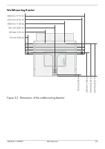
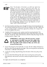
5. Insert two stainless-steel lag screws through the holes in the horizontal part of
the wall-mounting bracket and into the holes you drilled in the wall. Tighten the
screws until the bracket is held firmly against the wall (see #1 in Figure 3-4).
Do not overtighten the screws.
6. Carefully lift the Sunny Boy into position near the mounting bracket. The
upside-down, U-shaped bracket attached to back of the Sunny Boy at the top
edge fits over the top edge of the bracket so that the Sunny Boy hangs from the
bracket (see #2 in Figure 3-4).
WARNING:To avoid injury, lift the Sunny Boy careful-
ly, and handle it carefully to prevent the weight of the
inverter from causing you to lose your balance and
fall. If possible, have someone help you when you
mount the Sunny Boy.
7. Inspect the Sunny Boy from both sides to ensure that the U-shaped bracket on
the Sunny Boy fully engages the top edge of the mounting bracket and that the
Sunny Boy is centered on the bracket.
8. Locate the mounting strap that hangs from the back of the Sunny Boy at the
bottom.
9. Insert an M6x10 bolt through the hole in the mounting strap and into the
threaded hole in the bottom end of the wall-mounting bracket (see #3 in Figure
3-4).
10. Tighten the bolt fully (do not overtighten).
Summary of Contents for Sunny Boy SB 700U
Page 1: ...Sunny Boy SB 700U Installation Guide Version 1 1 SB700U 11 SE3207 TBE SB07U...
Page 2: ...ii SMA America SB700U 11 SE3207...
Page 14: ...1 6 SMA America SB700U 11 SE3207...
Page 16: ...2 2 SMA AmericaSB700U 11 SE3207...
Page 24: ...3 8 SMA America SB700U 11 SE3207 11 Verify that the Sunny Boy 700U is firmly mounted in place...
Page 46: ...4 22 SMA America SB700U 11 SE3207...
Page 50: ...6 2 SMA America SB700U 11 SE3207 Figure 6 1 The Sunny Boy LED Status Indicator...
Page 84: ...8 6 SMA America SB700U 11 SE3207...
Page 85: ......

