SMA
Technologie AG
Rating for a Line Circuit Breaker
Installation Guide
SB25_30-11:SE0307
Page 57
Summary
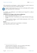
The selected line circuit breaker cannot be used in our example case since the maximum
current-carrying capacity for fault-free operation is lower than the maximum output
current of the inverter used.
It will trip under rated operating conditions!
In this case one solution would be to ensure there is an 8 mm gap between the circuit
breakers. This would mean that the reduction factor is 0.98 instead of 0.77. As a result,
the maximum current-carrying capacity would be 15.1 A.
In addition to the thermal rating of the circuit breakers, the boundary conditions as laid
out in section "Rating for a Line Circuit Breaker in a Photovoltaic Power Generating
System Operated in Parallel to the Low Voltage Grid" (page 16) and the applicable
DIN VDE standards also need to be taken into account. The main ones that apply here
are:
•
DIN VDE 0100, part 410
•
DIN VDE 0100, part 430
•
DIN VDE 0298, part 4
In special applications the relevant standards must be followed!
Summary of Contents for Sunny Boy SB 2500
Page 2: ......
Page 6: ...Explanation of the Symbols Used SMA Technologie AG Page 6 SB25_30 11 SE0307 Installation Guide...
Page 10: ...Safety Instructions SMA Technologie AG Page 10 SB25_30 11 SE0307 Installation Guide...
Page 20: ...Installation Requirements SMA Technologie AG Page 20 SB25_30 11 SE0307 Installation Guide...
Page 62: ...The Communication Interface SMA Technologie AG Page 62 SB25_30 11 SE0307 Installation Guide...
Page 65: ......


