7 Electrical Connection
SMA Solar Technology AG
Operating manual
SB55-LV-JP-41-BE-en-13
35
NOTICE
Damage to the inverter due to ground fault on DC side during operation
Due to the transformerless topology of the product, the occurance of ground faults on DC side
during operation can lead to irreparable damage. Damages to the product due to a faulty or
damaged DC installation are not covered by warranty. The product is equipped with a protective
device that checks whether a ground fault is present during the starting sequence. The product is
not protected during operation.
• Ensure that the DC installation is carried out correctly and no ground fault occurs during
operation.
Grounding cable requirements (optional):
Use of fine-stranded conductors
You can use an inflexible or a flexible, fine-stranded conductor.
• When using a fine-stranded conductor, it has to be double crimped by a ring terminal lug.
Make sure that no insulated conductor is visible when pulling or bending. This will ensure
sufficient strain relief by means of the ring terminal lug.
☐ Grounding cable cross-section: max. 8 mm²
Procedure:
1. Ensure that the circuit breaker is switched off and that it cannot be reconnected.
2. If an external DC load-break switch is installed, disconnect the external DC load-break switch
from all voltage sources.
3. Set the DC load-break switch of the inverter to
position
O
.
4. Measure the PV array voltage. Ensure that the maximum input voltage of the inverter is
adhered to and that there is no ground fault in the PV array.
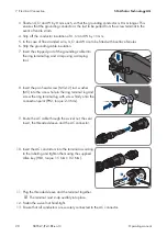
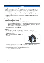
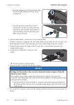
5. Proceed as follows to connect a grounding conductor (optional):
• Strip the grounding cable insulation.

