

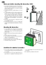
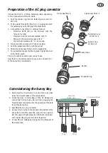


GB
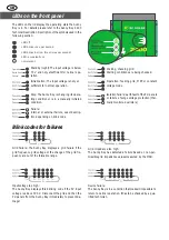
The LEDs on the lid display the operating state the Sunny
Boy is in. For details please refer to the Sunny Boy 2400
Technical Description. Description of the symbols used in the
following section:
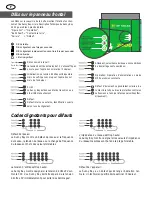
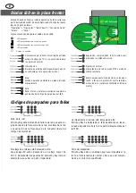
LEDs on the front panel
Blink codes for failures
Grid failure: The Sunny Boy displays a grid failure if the
grid frequency, grid voltage or the change of the grid fre-
quency are out of the tolerable range.
Grid impedance too high:
The Sunny Boy has detected a failure based on non-per-
missible grid impedance values measured by the MSD.
Input voltage too high:
The Sunny Boy displays this blinking code if the PV input
voltage is above 300 V. Disconnect the grid and then the
PV-panels from the Sunny Boy immediately to prevent da-
mage!
Device failure:
The Sunny Boy is in a condition that makes it impossible to
return to normal operation. It has to be checked by a qua-
lified technician.
LED off
LED blinks once per second
LED blinks fast (ca. three times per second)
LED is constantly on
not relevant
Operation
Earth Fault
Failure
Standby (night): The input voltage is below
70 V and not yet sufficient for normal ope-
ration.
Initialization: The input voltage is not yet
sufficient for normal operation.
Stop: The Sunny Boy is changing its opera-
ting condition or is in a manually initiated
condition.
Waiting, checking grid:
Starting conditions are being checked.
Operation: feeding grid, MPP or constant
voltage mode
Isolation failure: earth fault of the PV-panels
or failure of surge voltage protection (ther-
mally monitored varistors)
Failure:
internal or external failure, exact descrip-
tion depending on blink code
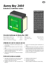
Summary of Contents for Sunny Boy 2400
Page 1: ......
Page 18: ...SB2400 10 QX2601...


