background image

3  Grid Failure

SMA Solar Technology AG

Technical Information

STP60-SHP75-10-Parameter-TI-en-12

8

3.2

Phase Failure Detection

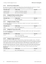
The phase failure detection is used to determine the failure of one or more line conductors of the utility grid. In case of
a grid failure, the grid relays open.

Parameter name

Setting options

OPEN_PH_DETECT

on (1)

off (0)

The ramp-in factor describes the ramp for the power up of the inverter. More details can be found in the settings for
grid management services under parameter 

Connection/reconnection ramp rate

.

3.3

Rate of Change of Frequency

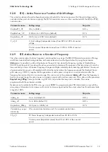
The parameter 

RoCoF

 or 

Rate of Change of Frequency

 measures the change in frequency. If the change in

frequency exceeds the stated maximum limit for a longer period of time, the inverter disconnects from the utility grid.
The frequency can change very rapidly if one or several line conductors fail.

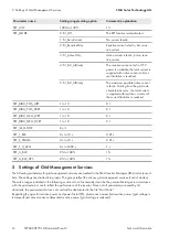
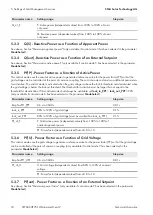
Parameter name

Setting range

Step size

LOM_ROC

0 Hz/s to 10 Hz/s

0.01 Hz/s

LOM_ROC

0 Hz/s to 10 Hz/s

0.01 Hz/s

T_LOM_ROC

0 s to 1800 s

0.01 s

LOM_ROC_THR

0 Hz to 5.0 Hz

0.01 Hz

Summary of Contents for SHP 75-10

Page 1: ...2 F3 F4 Hom e Back OK F1 F2 F3 F4 Hom e Back OK STP60 SHP75 10 Parameter TI en 12 Version 1 2 ENGLISH Technical Information SUNNY TRIPOWER 60 SUNNY HIGHPOWER PEAK1 Description of the Operating Paramet...

Page 2: ...4 Settings of Grid Management Services Fault Ride Through FRT 9 5 Settings of Grid Management Services 12 5 1 Default Settings 13 5 1 1 Selecting the Control Modes for Reactive Power Provision 13 5 1...

Page 3: ...STP60 SHP75 10 Parameter TI en 12 5 3 6 PF U Power Factor as a Function of Grid Voltage 18 5 3 7 PF ext Power Factor as a Function of an External Setpoint 18 5 3 8 P V Active Power as a Function of Gr...

Page 4: ...minal Voltage This parameter refers to the nominal grid voltage of a country In most countries only one official grid voltage is valid For countries with several official grid voltages additional grid...

Page 5: ...the three key values is used in your file Parameter name Setting range Step size UMAX UNOM to 350 Vac L N 0 1 Vac L N T_UMAX 0 05 s to 90 0 s 0 01 s 2 4 Manual Restart With the function Manual Restar...

Page 6: ...e key values is used in your file Parameter name Setting range Step size FMIN 45 Hz to FNOM 0 01 Hz T_FMIN 0 05 s to 90 0 s 0 01 s 2 5 2 Disconnection due to Overfrequency The overfrequency disconnect...

Page 7: ...to alarm is the period which the inverter must wait before generating an alarm event This is to prevent the inverter from generating alarm events all the time Parameter name Setting range Step size T_...

Page 8: ...tails can be found in the settings for grid management services under parameter Connection reconnection ramp rate 3 3 Rate of Change of Frequency The parameter RoCoF or Rate of Change of Frequency mea...

Page 9: ...gs to grid management services it is stored in the inverter The FRT function is set to cope with voltage dips down to 0 UNOM without time limit This is confirmed in the FRT performance test which was...

Page 10: ...e compared with the average root mean square values before the fault The relevant time frame for the average voltage before the grid fault can be set via the parameter FRT_T_U_AVG default 10 minutes F...

Page 11: ...as the total current does not exceed the limit After fault clearance reactive current feed in stays active for a certain transition period This period can be set with the grid code parameter FRT_T_TR...

Page 12: ...1 to 10 0 1 FRT_DIDU_POS_HVRT 1 to 10 0 1 FRT_DIDU_NEG_LVRT 1 to 10 0 1 FRT_DIDU_NEG_HVRT 1 to 10 0 1 FRT_IQ_MODE 0 or 1 FRT_T_BLK 0 s to 10 s 0 01 s FRT_T_TRANS 0 s to 10 s 0 01 s FRT_T_U_AVG 0 s to...

Page 13: ...for Reactive Power Provision Reactive power references can either be given as a direct reference for reactive power Q or as an indirect reference via the power factor PF The references are based on th...

Page 14: ...ng option P_LIM_IF_Q 80 to 100 default 100 5 1 4 Nominal Apparent Power at Point of Common Coupling PCC All grid management services in the inverter are based on the nominal apparent power at the poin...

Page 15: ...onnection see Section 2 Grid Protection Settings page 4 Parameter name Setting option Explanation ReleaseToStart 0 Immediate disconnection 1 Connection when grid parameter is in the permissible range...

Page 16: ...dicates the setpoint for the power factor PF only available if control mode 9 has been selected in the parameter ModeSelect Parameter name Setting range Step size PF_ref 0 8 to 1 0 for overexcitation...

Page 17: ...espectively 5 3 1 Q U Reactive Power as a Function of Grid Voltage This control mode uses the grid voltage to generate a reference value for the reactive power so that the grid voltage can be controll...

Page 18: ...w the lock out threshold The threshold for activation must be larger than or equal to the threshold for deactivation If this control mode shall always be available set lock_in_PPF lock_out_PPF 90 only...

Page 19: ...ose of this time delay is to reach a lower sensitivity in terms of transient frequency changes and higher reliability when detecting grid failures The amount of generated active power is still sampled...

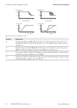
Page 20: ...c curves in the reference table contain equal co or dinates x y B Example of programming the FP_of_f characteristic curve when hysteresis is required e g as per BDEW Thus the two characteristic curves...

Page 21: ......

Page 22: ...www SMA Solar com...

Reviews: