6 Electrical Connection
SMA Solar Technology America LLC
Installation Manual
RSS-US-IA-xx-14
25
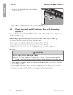
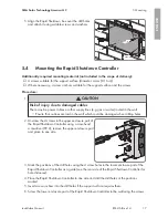
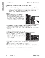
12. Plug the five-pole plug with the connected
conductors into the lower pin row of the terminal
block
RSC
.
13. If there is only one Rapid Shutdown Box in the
system, plug the second five-pole plug into the upper
row of the terminal block
RSC
and place a jumper
wire between pins 3 and 4. Here, use a jumper wire
that is rated for the maximum system voltages or
insulate the jumper wire using a piece of one of the
supplied silicone tubes.
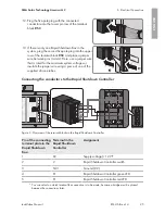
Connecting the conductors to the Rapid Shutdown Controller
+ A −
−
B +
RSC
NC
1
2
X
1
2
X
X
1
2
X
NC
1
2
X
1
2
X
X
1
2
X
1
2
3
4
5
Figure 9 : Overview of the terminal blocks in the Rapid Shutdown Controller
Pin of the connecting
terminal plate in the
Rapid Shutdown
Box
Terminal in the
Rapid Shutdown
Controller
Assignment
1
X2
Supply voltage (+12 V)*
2
2
Rapid Shutdown Controller switch
3
NC 1
Ground (0 V)
4
X1
Rapid Shutdown Controller green LED
5
X1
Rapid Shutdown Controller red LED
* You can select on which terminal the connection is to be made, because a bridge must be placed
between the connections later.
ENGLISH
Summary of Contents for RSB-2S-US-10
Page 132: ...www SMA Solar com...

