background image

RSS-US-IA-xx-14

131

2

Informations sur le respect des spécifications

FCC Compliance

This device complies with Part 15 of the FCC Rules.
Operation is subject to the following two conditions:

1. this device may not cause harmful interference, and
2. this device must accept any interference received, including interference that may cause

undesired operation.

NOTE: This equipment has been tested and found to comply with the limits for a Class B digital
device, pursuant to Part 15 of the FCC Rules. These limits are designed to provide reasonable
protection against harmful interference in a residential installation. This equipment generates, uses
and can radiate radio frequency energy and, if not installed and used in accordance with the
instructions, may cause harmful interference to radio communications. However, there is no
guarantee that interference will not occur in a particular installation. If this equipment does cause
harmful interference to radio or television reception, which can be determined by turning the
equipment off and on, the user is encouraged to try to correct the interference by one or more of
the following measures:

• Reorient or relocate the receiving antenna.
• Increase the separation between the equipment and receiver.
• Connect the equipment into an outlet on a circuit different from that to which the receiver is

connected.

• Consult the dealer or an experienced radio/TV technician for help.

Changes or modifications made to this equipment not expressly approved by SMA Solar
Technology America LLC may void the FCC authorization to operate this equipment.

IC Compliance

This Class B digital apparatus complies with Canadian ICES-003.
Cet appareil numérique de la classe B est conforme à la norme NMB-003 du Canada.

Summary of Contents for RSB-2S-US-10

Page 1: ...RSS US IA xx 14 101996 00 02 Version 1 4 SMA RAPID SHUTDOWN SYSTEM ENGLISH Installation Manual ESPA OL Instrucciones de instalaci n FRAN AIS Instructions d installation...

Page 2: ...to make this document complete accurate and up to date Readers are cautioned however that product improvements and field usage experience may cause SMA Solar Technology America LLC and or SMA Solar Te...

Page 3: ...rformed or adhered to could result in damage to or destruction of part or all of the SMA equipment and or other equipment connected to the SMA equipment or personal injury Symbol Description DANGER in...

Page 4: ...and use of the product including without limitation applicable electrical safety codes All installations must conform with the laws regulations codes and standards applicable in the jurisdiction of in...

Page 5: ...Controller 17 6 Electrical Connection 18 6 1 Safety during Electrical Connection 18 6 2 Overview of the Rapid Shutdown Box Connection Area 19 6 2 1 Exterior View 19 6 2 2 Interior View 20 6 3 Connect...

Page 6: ...ntents SMA Solar Technology America LLC Installation Manual RSS US IA xx 14 6 11 Technical Data 40 11 1 Rapid Shutdown Box 40 11 2 Rapid Shutdown Controller 40 12 Contact 42 13 Compliance Information...

Page 7: ...ctrical devices and installations Training in the installation and commissioning of electrical devices and installations Knowledge of the applicable standards and directives Knowledge of and complianc...

Page 8: ...id Shutdown Box is defective The product is certified for use in PV systems with the following SMA inverters SB 3000TL US 22 SB 3800TL US 22 SB 4000TL US 22 SB 5000TL US 22 SB 6000TL US 22 SB 7000TL U...

Page 9: ...ates dangerous DC voltage which is present in the DC conductors Touching the DC conductors can lead to lethal electric shocks Disconnect the DC connectors on the input strings Have the product mounted...

Page 10: ...1 Components included in the scope of delivery Position Quantity Designation A 1 Rapid Shutdown Box B 3 Spring lock washer C 2 Clamping bracket D 3 Washer E 1 Hex nut F 2 Cylindrical screw G 1 Clampi...

Page 11: ...the Rapid Shutdown Controller to 30 V This is done by the disconnection of the PV array on the input side of the Rapid Shutdown Box while the stored leading energy of the inverters is discharged simul...

Page 12: ...wn Controller Figure 3 Design of the Rapid Shutdown Box and Rapid Shutdown Controller Position Designation A DC connection for the input strings B Rapid Shutdown Box type label C Rapid Shutdown Contro...

Page 13: ...rectly on the roof or on a wall Here there must be a distance of at least 13 mm 0 5 in between the Rapid Shutdown Box and the module backsheet and the permissible cable length between the PV array and...

Page 14: ...n Box and Rapid Shutdown Controller may only be mounted in a permissible position This ensures that moisture can not penetrate the Rapid Shutdown Box or Rapid Shutdown Controller Figure 5 Permitted an...

Page 15: ...ews being too long The length of the screws must be suitable for the distance between the Rapid Shutdown Box and the underside of the PV module Make sure that the PV module will not be damaged by the...

Page 16: ...rews suitable for the support surface diameter 8 mm 0 3 in 4 washers suitable for the screws outer diameter 16 mm 0 6 in Where necessary 4 screw anchors suitable for the support surface and the screws...

Page 17: ...routed in the wall Ensure that no lines are laid in the wall which could be damaged when drilling holes 2 Unscrew the 4 screws in the upper enclosure part of the Rapid Shutdown Controller using a cro...

Page 18: ...e types of seals are not reliable for this application Seal all unused openings tightly Electrical installations All electrical installations must be carried out in accordance with the local standards...

Page 19: ...nd 4 channel B C Connection point for the equipment grounding conductor D Enclosure opening for the Rapid Shutdown Controller conductors and where necessary for the conductors of an additional Rapid S...

Page 20: ...connection of the second output string channel B 6 3 Connecting the Equipment Grounding Conductor to the Rapid Shutdown Box Each Rapid Shutdown Box can be grounded separately or several Rapid Shutdown...

Page 21: ...e a spring lock washer and a hex nut onto the thread and tighten the hex nut torque 3 5 Nm 31 in lb 5 NOTICE Prevention of contact corrosion by bending the equipment grounding conductor The equipment...

Page 22: ...e Rapid Shutdown Controller are laid in one conduit together with the output strings the conductors for the connection of the Rapid Shutdown Controller must be insulated for the maximum PV system volt...

Page 23: ...t To do so first connect one end of the conductors to the Rapid Shutdown Box and then connect the other end of the conductors to the Rapid Shutdown Controller Connect the conductors to the Rapid Shutd...

Page 24: ...ing 4 Insert the conduit fitting into the opening on the Rapid Shutdown Box and tighten from the inside using the counter nut 5 Attach the conduit at the conduit fitting in the Rapid Shutdown Box encl...

Page 25: ...mper wire using a piece of one of the supplied silicone tubes Connecting the conductors to the Rapid Shutdown Controller A B RSC NC 1 2 X 1 2 X X 1 2 X NC 1 2 X 1 2 X X 1 2 X 1 2 3 4 5 Figure 9 Overvi...

Page 26: ...ut on the Rapid Shutdown Controller and tighten from the inside using the counter nut 3 Attach the conduit to the conduit fitting or onto the adapter in the Rapid Shutdown Controller enclosure 4 Lead...

Page 27: ...s together Additionally required material not included in the scope of delivery Conduit trade size 16 mm 0 5 in or smaller with suitable reducer bush Raintight or liquidtight conduit fitting trade siz...

Page 28: ...ectrical standards and the National Electrical Code ANSI NFPA 70 or the Canadian Electrical Code CSA C22 1 Pin assignment Figure 10 Pin assignment of the upper pin row on the terminal block RSC in the...

Page 29: ...e together securely 10 Plug the five pole plug with the connected conductors into the upper pin row of the terminal block RSC 11 Connect the Rapid Shutdown Boxes together To do so connect the incoming...

Page 30: ...ted to different inverters Connect only output strings to the terminal block A and B which are leading to the same inverter Procedure Connect the output strings Connect the input strings Connecting th...

Page 31: ...of the second output string up to the terminal block B 6 Lead the existing equipment grounding conductors of the output strings to the equipment ground bar and connect them Strip the insulation of th...

Page 32: ...to the stop and insert the conductors into the terminals When doing so ensure that the positive terminal and negative terminal have the correct polarity at the inverter 11 CAUTION Danger of pinching f...

Page 33: ...to life due to high voltages When exposed to sunlight the PV array generates dangerous DC voltage which is present in the DC conductors Touching the DC conductors can lead to lethal electric shocks En...

Page 34: ...arts feed in operation If the inverters display no errors and start feed in operation the Rapid Shutdown System is connected correctly and automatically commissioned If the inverters do not start feed...

Page 35: ...roller glows constantly The green LED on the Rapid Shutdown Controller glows constantly The Rapid Shutdown System is active and the voltages on the output string side of the Rapid Shutdown Box are 30...

Page 36: ...of the Rapid Shutdown System is faulty or the Rapid Shutdown Box is defective Make sure that the supply voltage of the Rapid Shutdown System is sufficient Ensure that the Rapid Shutdown System is ins...

Page 37: ...tors of the Rapid Shutdown Controllers and if present those of an additional Rapid Shutdown Box from the Rapid Shutdown Box To do so pull the respective five pole plugs with the connected conductors o...

Page 38: ...nscrew the screws for attachment using a suitable screwdriver and remove the Rapid Shutdown Box from the rack rail from the wall or from the roof 11 Unscrew the 4 screws in the upper enclosure part of...

Page 39: ...id Shutdown System SMA Solar Technology America LLC Installation Manual RSS US IA xx 14 39 15 Place the upper enclosure part onto the lower enclosure part and tighten the four screws using a cross hea...

Page 40: ...4 in x 3 in Length x width x height of the packaging 770 mm x 395 mm x 125 mm 30 3 in x 15 5 in x 4 9 in Weight of the Rapid Shutdown Box without packaging 3 8 kg 8 4 lb Weight of the Rapid Shutdown...

Page 41: ...y America LLC Installation Manual RSS US IA xx 14 41 Maximum operating altitude above mean sea level MSL 3000 m 9843 ft Enclosure degree of protection according to UL 50 4X Torque of the upper enclosu...

Page 42: ...ce Serial number of the Rapid Shutdown Box Serial number of the Rapid Shutdown Controller United States Esta dos Unidos SMA Solar Technology America LLC Rocklin CA Toll free for USA Canada and Puerto...

Page 43: ...ons may cause harmful interference to radio communications However there is no guarantee that interference will not occur in a particular installation If this equipment does cause harmful interference...

Page 44: ...os de hacer que este documento sea completo y preciso y est actualizado Sin embargo advertimos a los lectores que SMA Solar Technology America LLC y SMA Solar Technology Canada Inc se reservan el dere...

Page 45: ...causar lesiones al usuario o da os materiales Llama la atenci n sobre un procedimiento o una actividad que de no realizarse correctamente puede causar lesiones al usuario o da os materiales en product...

Page 46: ...chnology America LLC Instrucciones de instalaci n RSS US IA xx 14 46 Observar las instrucciones de uso Lea la documentaci n del producto antes de trabajar con l Siga todas las precauciones e instrucci...

Page 47: ...elativas a la seguridad el ctrica La instalaci n debe llevarse a cabo de conformidad con la legislaci n las disposiciones los reglamentos y las normas vigentes en el lugar SMA no asume responsabilidad...

Page 48: ...taje del Rapid Shutdown Controller 60 6 Conexi n el ctrica 61 6 1 Seguridad en la conexi n el ctrica 61 6 2 Vista general de las reas de conexi n de la Rapid Shutdown Box 62 6 2 1 Vista exterior 62 6...

Page 49: ...strucciones de instalaci n RSS US IA xx 14 49 10 Puesta fuera de servicio del Rapid Shutdown System 80 11 Datos t cnicos 83 11 1 Rapid Shutdown Box 83 11 2 Rapid Shutdown Controller 83 12 Contacto 85...

Page 50: ...el manejo de equipos el ctricos y plantas Formaci n profesional para la instalaci n y la puesta en marcha de equipos el ctricos y plantas Conocimiento de las normativas y directivas aplicables Conocim...

Page 51: ...wn Box est averiada El producto est autorizado para usarse en plantas fotovoltaicas con estos inversores de SMA SB 3000TL US 22 SB 3800TL US 22 SB 4000TL US 22 SB 5000TL US 22 SB 6000TL US 22 SB 7000T...

Page 52: ...ue se acopla a los conductores de CC El contacto con dichos conductores de CC puede causar descargas el ctricas mortales Desconecte los conectadores de enchufe de CC de los strings de entrada Encargue...

Page 53: ...Componentes del contenido de la entrega Posici n Cantidad Denominaci n A 1 Rapid Shutdown Box B 3 Arandela el stica C 2 Abrazadera D 3 Arandela E 1 Tuerca hexagonal F 2 Tornillo cil ndrico G 1 Abraza...

Page 54: ...emergencia en el Rapid Shutdown Controller Esto se realiza a trav s de la separaci n del generador fotovoltaico en el lado de entrada de la Rapid Shutdown Box al tiempo que se descarga la energ a alm...

Page 55: ...Estructura de la Rapid Shutdown Box y del Rapid Shutdown Controller Posici n Denominaci n A Conexi n de CC de los strings de entrada B Placa de caracter sticas de la Rapid Shutdown Box C Placa de cara...

Page 56: ...fotovoltaico directamente sobre el tejado o en una pared Para ello entre la Rapid Shutdown Box y la parte posterior del m dulo debe respetarse una distancia m nima de 13 mm 0 5 in y la longitud de ca...

Page 57: ...idas La Rapid Shutdown Box y el Rapid Shutdown Controller deben instalarse siempre en una posici n autorizada para garantizar que no entre humedad Imagen 5 Posiciones de montaje permitidas y no permit...

Page 58: ...a o del m dulo fotovoltaico por tornillo demasiado largo La longitud del tornillo debe ser adecuada para la distancia entre la Rapid Shutdown Box y la parte de abajo del m dulo fotovoltaico Aseg rese...

Page 59: ...rnillos adecuados para la superficie di metro 8 mm 0 31 in Cuatro arandelas adecuadas para los tornillos di metro exterior 16 mm 0 6 in En su caso cuatro tacos adecuados para la superficie y los torni...

Page 60: ...ejemplo de gas o de agua Aseg rese de que no haya cables oempotrados en la pared que pueda da ar al taladrar 2 Quite los cuatro tornillos de la parte superior de la carcasa del Rapid Shutdown Controll...

Page 61: ...junta no ofrece la fiabilidad necesaria para esta aplicaci n Cierre de manera estanca las aberturas que no utilice Instalaciones el ctricas Todas las instalaciones el ctricas deben realizarse conform...

Page 62: ...de conexi n para el conductor de puesta a tierra del equipo D Abertura en la carcasa para los conductores del Rapid Shutdown Controller y en caso necesario para los conductores de una Rapid Shutdown...

Page 63: ...g de salida Channel B 6 3 Conexi n del conductor de puesta a tierra del equipo a la Rapid Shutdown Box Puede poner a tierra cada Rapid Shutdown Box por separado o conectar varias Rapid Shutdown Box co...

Page 64: ...la el stica y 1 tuerca hexagonal sobre la rosca y apriete la tuerca hexagonal par de apriete 3 5 Nm 31 in lb 5 PRECAUCI N Prevenci n de la corrosi n por contacto si se curva el conductor de puesta a t...

Page 65: ...exi n del Rapid Shutdown Controller est n tendidos en un conducto para cables junto con los strings de salida los conductores para la conexi n del Rapid Shutdown Controller deben estar aislados para l...

Page 66: ...n extremo de los conductores a la Rapid Shutdown Box y a continuaci n el otro extremo de los conductores al Rapid Shutdown Controller Conecte los conductores a la Rapid Shutdown Box Conecte los conduc...

Page 67: ...de la abertura en la carcasa 4 En la Rapid Shutdown Box introduzca el manguito en la abertura y f jelo desde el interior con la contratuerca 5 Fije el conducto para cables al manguito en la carcasa d...

Page 68: ...tema o a sle la ligadura de alambre con un trozo de tubo de silicona de uno de los tubos suministrados Conexi n de los conductores al Rapid Shutdown Controller A B RSC NC 1 2 X 1 2 X X 1 2 X NC 1 2 X...

Page 69: ...omercial 16 mm 0 5 in 2 Dado el caso coloque en el Rapid Shutdown Controller el adaptador suministrado en la posici n deseada y f jelo desde el interior con la contratuerca 3 Fije el conducto para cab...

Page 70: ...ctar entre s las Rapid Shutdown Box debe proceder seg n se describe a continuaci n Como m ximo se pueden conectar entre s 16 Rapid Shutdown Box Material adicional necesario no incluido en el contenido...

Page 71: ...edad Requisito Todas las instalaciones el ctricas deben realizarse conforme a la normativa local vigente y al c digo National Electrical Code ANSI NFPA 70 o al Canadian Electrical Code CSA C22 1 Asign...

Page 72: ...el conector de cinco polos con los conductores conectados en la fila superior de patillas de la caja de bornes RSC 11 Conecte entre s las Rapid Shutdown Box Para ello conecte los conductores de entra...

Page 73: ...to de como m nimo un inversor est averiado Conecte en la caja de bornes A y B solamente string de salida que conduzcan al mismo inversor Procedimiento Conecte los strings de salida Conecte los strings...

Page 74: ...bornes A 5 Introduzca los conductores positivo y negativo del segundo string de salida en la caja de bornes B 6 Conecte los conductores de puesta a tierra del equipo disponibles de los strings de sal...

Page 75: ...ci n e introduzca los conductores en los bornes Aseg rese de que los polos positivo y negativo est n conectados con la polaridad correcta en el inversor 11 ATENCI N Peligro de aplastamiento de los ded...

Page 76: ...or altas tensiones Cuando recibe luz solar el generador fotovoltaico produce una tensi n de CC peligrosa que se acopla a los conductores de CC El contacto con dichos conductores de CC puede causar des...

Page 77: ...funcionamiento de inyecci n Si el inversor no muestra un error e inicia el funcionamiento de inyecci n el Rapid Shutdown System est correctamente conectado y se pone en marcha de forma autom tica Si...

Page 78: ...ndido El led verde del Rapid Shutdown Controller permanece encendido El Rapid Shutdown System est activado y las tensiones en el lado de los strings de salida de la Rapid Shutdown Box son 30 V No se e...

Page 79: ...seg rese de que la tensi n de alimentaci n del Rapid Shutdown System sea suficiente Aseg rese de que la instalaci n del Rapid Shutdown System se haya realizado correctamente Si la tensi n de alimentac...

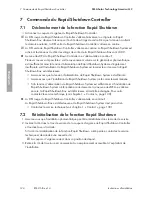
Page 80: ...X 25 y retire la tapa 3 Extraiga de la Rapid Shutdown Box los conductores del Rapid Shutdown Controller y en su caso de una Box adicional Para ello extraiga cada uno de los conectores de cinco polos c...

Page 81: ...suelte los tornillos para la fijaci n con un destornillador adecuado y retire la Rapid Shutdown Box del carril de perfil de la pared o del tejado 11 Quite los cuatro tornillos de la parte superior de...

Page 82: ...SMA Solar Technology America LLC Instrucciones de instalaci n RSS US IA xx 14 82 15 Coloque la parte superior de la carcasa encima de la parte inferior de la carcasa y apriete los cuatro tornillos co...

Page 83: ...21 3 in x 13 4 in x 3 in Longitud x anchura x altura del embalaje 770 mm x 395 mm x 125 mm 30 3 in x 15 5 in x 4 9 in Peso de la Rapid Shutdown Box sin embalaje 3 8 kg 8 4 lb Peso de la Rapid Shutdown...

Page 84: ...trucciones de instalaci n RSS US IA xx 14 84 Altitud de funcionamiento m xima sobre el nivel del mar 3000 m 9843 ft Tipo de protecci n de la carcasa seg n UL50 4X Par de apriete de los tornillos de la...

Page 85: ...s datos N mero de serie de la Rapid Shutdown Box N mero de serie del Rapid Shutdown Controller United Sta tes Estados Unidos SMA Solar Technology America LLC Rocklin CA Toll free for USA Canada and Pu...

Page 86: ...instructions may cause harmful interference to radio communications However there is no guarantee that interference will not occur in a particular installation If this equipment does cause harmful in...

Page 87: ...rand soin et tenu aussi jour que possible SMA Solar Technology America LLC et ou SMA Solar Technology Canada Inc avertissent toutefois les lecteurs qu elles se r servent le droit d apporter des modifi...

Page 88: ...Dispositions l gales SMA Solar Technology America LLC Instructions d installation RSS US IA xx 14 88 tat actuel 29 08 2017 Copyright 2017 SMA Solar Technology America LLC Tous droits r serv s FRAN AIS...

Page 89: ...a nant des blessures corporelles ou dommages mat riels La mise en garde indique une action qui risque les blessures corporelles ou les dommages mat riels aux produits SMA ou aux produits raccord s en...

Page 90: ...Instructions d installation RSS US IA xx 14 90 Consulter les instructions d utilisation Lisez la documentation relative au produit avant de travailler sur ce dernier Respectez toutes les consignes de...

Page 91: ...mment les normes en vigueur relatives la s curit lectrique L installation doit tre r alis e conform ment aux l gislations dispositions prescriptions et normes en vigueur sur place SMA d cline toute re...

Page 92: ...pid Shutdown Controller 104 4 Raccordement lectrique 105 4 1 S curit lors du raccordement lectrique 105 4 2 Vue d ensemble des zones de raccordement de la Rapid Shutdown Box 106 4 2 1 Vue ext rieure 1...

Page 93: ...tions d installation RSS US IA xx 14 93 8 Mise hors service du Rapid Shutdown System 125 9 Caract ristiques techniques 128 9 1 Rapid Shutdown Box 128 9 2 Rapid Shutdown Controller 128 1 Contact 130 2...

Page 94: ...rs de l installation et de la manipulation d appareils et installations lectriques Formation l installation et la mise en service des appareils et installations lectriques Connaissance des normes et d...

Page 95: ...ctueuse Le produit convient l utilisation dans les installations photovolta ques dot es des onduleurs SMA suivants SB 3000TL US 22 SB 3800TL US 22 SB 4000TL US 22 SB 5000TL US 22 SB 6000TL US 22 SB 70...

Page 96: ...ovolta que En cas d ensoleillement le g n rateur photovolta que produit une tension continue dangereuse dans les conducteurs DC Le contact avec les conducteurs DC peut entra ner des chocs lectriques s...

Page 97: ...uantit D signation A 1 Rapid Shutdown Box B 3 Rondelle ressort C 2 Serre c ble D 3 Rondelle E 1 crou six pans F 2 Vis t te cylindrique G 1 Serre c ble H 3 Bouchon d tanch it pour les connecteurs MC4 p...

Page 98: ...utdown Controller Cela est r alis en isolant le g n rateur photovolta que du c t de l entr e de la Rapid Shutdown Box tout en d chargent simultan ment l nergie capacitive accumul e des onduleurs Si le...

Page 99: ...ure 3 Structure de la Rapid Shutdown Box et du Rapid Shutdown Controller Position D signation A Raccordement DC pour les strings d entr e B Plaque signal tique de la Rapid Shutdown Box C Plaque signal...

Page 100: ...le toit ou sur un mur Un cart de 13 mm 0 5 in au moins doit tre respect entre la Rapid Shutdown Box et la face arri re du panneau et la longueur de c ble autoris e entre le g n rateur photovolta que e...

Page 101: ...Controller ne doivent tre mont s que dans la position autoris e Cela permet d viter que de l humidit ne p n tre dans la Rapid Shutdown Box et dans le Rapid Shutdown Controller Figure 5 Positions de m...

Page 102: ...DENCE Endommagement du panneau photovolta que par des vis trop longues La longueur des vis doit tre adapt e la distance entre la Rapid Shutdown Box et la face inf rieure du panneau photovolta que Assu...

Page 103: ...it tre en acier inoxydable 4 vis adapt es au support diam tre 8 mm 0 3 in 4 rondelles adapt es aux vis diam tre ext rieur 16 mm 0 6 in Le cas ch ant quatre chevilles adapt es au support et aux vis Pro...

Page 104: ...e de gaz ou d eau peuvent tre pos s dans le mur Assurez vous de ne pas endommager les c bles pos s au mur lors du per age 2 l aide d un tournevis cruciforme PZ 2 d vissez les 4 vis de la partie sup ri...

Page 105: ...requise pour cette application et ne sont donc pas autoris s Obturez herm tiquement les orifices inutilis s Installations lectriques Toutes les installations lectriques doivent tre r alis es conform...

Page 106: ...oint de raccordement pour le conducteur de mise la terre de l quipement D Ouverture de bo tier pour les conducteurs du Rapid Shutdown Controller et si n cessaire pour les conducteurs d une Rapid Shutd...

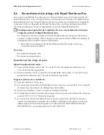
Page 107: ...ortie Channel B 4 3 Raccordement du conducteur de mise la terre de l quipement la Rapid Shutdown Box Vous pouvez mettre chaque Rapid Shutdown Box la terre s par ment ou relier plusieurs Rapid Shutdown...

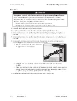
Page 108: ...et 1 crou six pans sur le filetage et serrez l crou six pans couple de serrage 3 5 Nm 31 in lb 5 PRUDENCE Emp chement de la corrosion par contact par pliage du conducteur de mise la terre de l quipem...

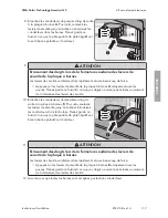
Page 109: ...Shutdown Controller les conducteurs doivent tre pos s avec les strings de sortie dans un tuyau c bles les conducteurs doivent tre isol s pour la tension maximale du syst me photovolta que Les conduct...

Page 110: ...re raccordez tout d abord une extr mit des conducteurs la Rapid Shutdown Box et ensuite l autre extr mit des conducteurs au Rapid Shutdown Controller Raccordez les conducteurs la Rapid Shutdown Box Ra...

Page 111: ...tier 4 Ins rez le manchon dans l ouverture de la Rapid Shutdown Box et vissez le de l int rieur avec le contre crou 5 Fixez le tuyau c bles au manchon dans le bo tier de la Rapid Shutdown Box 6 Ins r...

Page 112: ...le cavalier avec un morceau de gaine en silicone de l une des gaines en silicone fournies Raccordement des conducteurs au Rapid Shutdown Controller A B RSC NC 1 2 X 1 2 X X 1 2 X NC 1 2 X 1 2 X X 1 2...

Page 113: ...oit tre utilis 2 Le cas ch ant mettez l adaptateur fourni en place sur le Rapid Shutdown Controller l emplacement cass et vissez le de l int rieur avec le contre crou 3 Vissez le tuyau c bles sur le m...

Page 114: ...de la fa on suivante Vous pouvez raccorder au maximum 16 Rapid Shutdown Box les unes aux autres Mat riel suppl mentaire n cessaire non compris dans le contenu de livraison Tuyau c bles taille commerci...

Page 115: ...est tanche est qu aucune humidit ne peut p n trer Condition requise Toutes les installations lectriques doivent tre r alis es conform ment aux normes lectriques en vigueur sur le site et au National E...

Page 116: ...aine en silicone sont raccord s en fixe les uns l autre 10 Ins rez la fiche 5 p les avec les conducteurs raccord s dans la rang e de broches sup rieure de la plaque bornes RSC 11 Raccordez les Rapid S...

Page 117: ...ement des strings de sortie qui conduisent au m me onduleur Proc dure Raccordez les strings de sortie Raccordez les strings d entr e Raccordement des strings de sortie Mat riel suppl mentaire requis T...

Page 118: ...r de la Rapid Shutdown Box 4 Introduisez les conducteurs positif et n gatif du premier string de sortie jusqu la plaque bornes A 5 Introduisez les conducteurs positif et n gatif du deuxi me string de...

Page 119: ...nez garde ce faisant ce que vos doigts ne soient pas cras s au moment de la fermeture des leviers de s curit 10 Branchez les conducteurs du deuxi me string de sortie la plaque bornes B Pour cela soule...

Page 120: ...formations sur l assemblage des connecteurs voir instructions du connecteur Chaque conducteur DC n gatif d un string doit tre quip d un connecteur MC4 femelle informations sur l assemblage des connect...

Page 121: ...endommagement des connecteurs MC4 par p n tration d humidit L tanch it des conducteurs MC4 n est assur e que lorsque tous les connecteurs MC4 inutilis s qui d passent de la Rapid Shutdown Box sont ob...

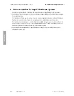
Page 122: ...le mode d injection Si l onduleur n affiche aucune erreur et que le mode d injection d marre le Rapid Shutdown System est commut correctement et est galement mis automatiquement en service Si l ondul...

Page 123: ...Controller s allume en continu Le Rapid Shutdown System est activ et les tensions du c t des strings de sortie de la Rapid Shutdown Box sont 30 V Aucune des DEL du Rapid Shutdown Controller ne s allum...

Page 124: ...d fectueuse Assurez vous que la tension d alimentation du Rapid Shutdown System est suffisante Assurez vous que l installation du Rapid Shutdown System a t correctement r alis e Si la tension d alimen...

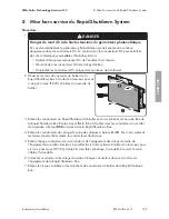
Page 125: ...pans creux TX 25 et retirez le couvercle du bo tier 3 Retirez les conducteurs du Rapid Shutdown Controller et le cas ch ant d une autre Box de la Rapid Shutdown Box Retirez cet effet la fiche 5 p les...

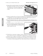
Page 126: ...ox D vissez cet effet selon le type de montage les vis de fixation l aide d un tournevis appropri et retirez la Rapid Shutdown Box du profil du mur ou du toit 11 l aide d un tournevis cruciforme PZ 2...

Page 127: ...stem SMA Solar Technology America LLC Instructions d installation RSS US IA xx 14 127 15 Mettez la partie sup rieure du bo tier en place sur la partie inf rieure du bo tier et serrez les 4 vis l aide...

Page 128: ...x 542 mm x 340 mm x 75 mm 21 3 in x 13 4 in x 3 in Longueur x largeur x hauteur de l emballage 770 mm x 395 mm x 125 mm 30 3 in x 15 5 in x 4 9 in Poids de la Rapid Shutdown Box sans embal lage 3 8 kg...

Page 129: ...US IA xx 14 129 Plage de temp rature de fonctionnement 25 C 70 C 13 F 158 F Altitude maximale d exploitation au dessus du niveau moyen de la mer 3000 m 9843 ft Indice de protection du bo tier selon U...

Page 130: ...Rapid Shutdown Box Num ro de s rie du Rapid Shutdown Controller United States Esta dos Unidos SMA Solar Technology America LLC Rocklin CA Toll free for USA Canada and Puerto Rico Llamada gra tuita en...

Page 131: ...nterference to radio communications However there is no guarantee that interference will not occur in a particular installation If this equipment does cause harmful interference to radio or television...

Page 132: ...www SMA Solar com...

Reviews: