background image

Installation Manual

SMC9-11TLRP-IA-en-51

41

SMA Solar Technology AG

6 Electrical Connection

WaHiw_Leerlaufspannung darf max. Eingangsspannung nicht überschreiten

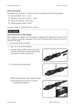
1. Disconnect the miniature circuit-breaker and secure against reconnection.

4. Check strings for earth faults. Checking the PV Plant for Earth Faults.

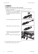
☑ The DC connectors click audibly into place.

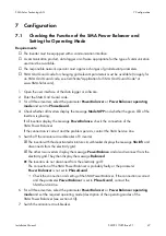
6.4.3

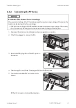
Connecting the PV Array

Destruction of the inverter due to overvoltage

If the open-circuit voltage of the PV modules exceeds the maximum input voltage of the inverter, the 
inverter can be destroyed by the overvoltage.

• If the open-circuit voltage of the PV modules exceeds the maximum input voltage of the inverter, 

do not connect any PV strings to the inverter and check the design of the PV plant.

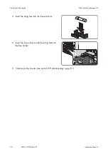
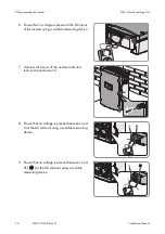
2. If the ESS is plugged in, remove the ESS.

3. Remove the filler plugs from all the DC inputs on 

the inverter.

5. Connect the assembled DC connectors to the 

inverter.

Summary of Contents for 10000TL

Page 1: ...Front cover PV Inverter SUNNY MINI CENTRAL 9000TL 10000TL 11000TL with Reactive Power Control Installation Manual SMC9 11TLRP IA en 51 IMEN SMCTLRP Version 5 1 ...

Page 2: ......

Page 3: ... 17 4 3 Display and LEDs 19 4 4 Electronic Solar Switch ESS 20 4 5 SMA Power Balancer 21 4 6 Communication 23 4 7 Grid Management 23 4 8 Fuse Holders for String Fuses 23 4 9 Varistors 24 4 10 SMA Grid Guard 24 4 11 All Pole Sensitive Residual Current Monitoring Unit 24 5 Mounting 25 5 1 Selecting the Mounting Location 25 5 2 Mounting the Inverter 28 6 Electrical Connection 31 6 1 Safety during Ele...

Page 4: ...ng the Function of the SMA Power Balancer and Setting the Operating Mode 47 7 2 Changing the Country Data Set 48 7 3 Setting the Country Data Set for Operation with External Decoupling Protection 49 7 4 Changing the Display Language 50 8 Commissioning 51 9 Disconnecting the Inverter 53 10 Troubleshooting 56 10 1 LED Signals 56 10 2 Display Messages 58 10 2 1 Measurement Channels 58 10 2 2 Status M...

Page 5: ...king the Inverter 81 11 3 Disposing of the Inverter 81 12 Technical Data 82 12 1 DC AC 82 12 1 1 Sunny Mini Central 9000TL with Reactive Power Control 82 12 1 2 Sunny Mini Central 10000TL with Reactive Power Control 84 12 1 3 Sunny Mini Central 11000TL with Reactive Power Control 86 12 2 General Data 88 12 3 Protective Devices 89 12 4 Approvals 89 12 5 Climatic Conditions 89 12 6 Features 90 12 7 ...

Page 6: ...Table of Contents SMA Solar Technology AG 6 SMC9 11TLRP IA en 51 Installation Manual ...

Page 7: ...on 2 2 Qualifications of Skilled Persons page 11 STSatz_Hinw_Weiterführende Informationen Additional Information Links to additional information can be found at www SMA Solar com STSatz_Hinw_Symbole 1 Information on this Document Document title Document type Three Phase Grid Connection Technical information Miniature Circuit Breaker Technical information Module Technology Technical information Ope...

Page 8: ...ury Indicates a situation which if not avoided could result in property damage Information that is important for a specific topic or goal but is not safety relevant Indicates a requirement for achieving a specific goal Desired result A problem that might occur Typography Usage Example Bold Display messages Parameter Connections Slots Elements to be selected Elements to be entered The inverter disp...

Page 9: ...ion AC Alternating Current DC Direct Current DSP Digital Signal Processor EC European Community EEPROM Electrically Eraseable Programmable Read Only Memory LED Light Emitting Diode MPP Maximum Power Point MSL Mean Sea Level OCU Operation Control Unit PC Personal Computer PE Protective Earth Protective conductor PV Photovoltaics RP Reactive Power ...

Page 10: ...le manufacturer for use with this Sunny Mini Central PV modules with a high capacity to earth should only be used if their coupling capacity does not exceed 1 400 nF All components must remain within their permitted operating ranges at all times National approval and release The product may only be used in countries for which it is approved or released by SMA Solar Technology AG and the network op...

Page 11: ...ugänglich The enclosed documentation is an integral part of this product Read and observe the documentation Keep the documentation in a convenient place for future reference The work described in this document must be performed by skilled persons only Skilled persons must have the following qualifications Knowledge of how an inverter works and is operated Training in how to deal with the dangers a...

Page 12: ... on the enclosure lid only Environmental Influences SiHiw_ESS_Dichtigkeit When closed and with the ESS plugged in the inverter has the degree of protection IP65 If the ESS is not plugged in or incorrectly plugged in during operation moisture and dust can penetrate the inverter If the ESS is not correctly plugged in this can cause contacts in the ESS to wear or the ESS might fall out of the socket ...

Page 13: ...livery is incomplete or damaged 3 Scope of Delivery Figure 2 Components of the delivery Position Quantity Designation A 1 Sunny Mini Central B 2 Ventilation grid C 1 Wall mounting bracket D 1 Electronic Solar Switch E 5 Positive DC connector F 5 Negative DC connector G 10 Sealing plug H 1 Cable gland I 1 Counter nut K 1 Clamping bracket L 2 Conical spring washer M 2 M6x16 cheese head screw N 1 Jum...

Page 14: ...pe of Delivery SMA Solar Technology AG Q 1 Installation manual user manual document set with explanations and certificates supplementary sheet with the default settings 1 spare part for the enclosure lid included Optional Position Quantity Designation ...

Page 15: ...ter which converts the direct current of the PV array to grid compliant alternating current and feeds it into the electricity grid 4 Product Description 4 1 Sunny Mini Central Figure 3 Design of the Sunny Mini Central Item Designation A Ventilation grid B Type label C Electronic Solar Switch ESS D LEDs E Display F Enclosure lid G Screws of the enclosure lid ...

Page 16: ...D The red LED indicates an earth fault a defective varistor or a defective string fuse Observe the documentation This symbol defines the function of the yellow LED which indicates a fault or disturbance Read the manual to remedy the fault or disturbance Protective conductor This symbol indicates the position for the protective conductor connection Danger to life due to high voltages in the inverte...

Page 17: ...eschreibung You require the information on the type label to use the product safely and for questions to the SMA Service Line The type label must be permanently attached to the product 4 2 Type Label Figure 4 Layout of the type label Item Explanation A Inverter device type B Inverter serial number C Device specific characteristics D Field for additional information e g details of standards E Inver...

Page 18: ...bserve the documentation Observe all documentation that is supplied with the inverter DC Direct current Without transformer The inverter does not have a transformer AC Alternating current Proper disposal Do not dispose of the inverter together with the household waste CE marking The inverter complies with the requirements of the applicable EU directives Degree of protection The inverter is protect...

Page 19: ...rean guidelines Chinese mark of conformity The inverter complies with the requirements of the applicable Chinese guidelines 4 3 Display and LEDs Figure 5 Design of the display Position Designation Explanation A Display 2 line LC text display for displaying operating data B Tap symbol You can operate the display by tapping it Tapping once Switch on display illumination or switch to the next display...

Page 20: ...r Removing the ESS interrupts the DC electric circuit and removing all DC connectors disconnects the PV array completely from the inverter 4 4 Electronic Solar Switch ESS Figure 6 Example of ESS design with visible metal mounting tab Item Designation Explanation A Plug Depending on the type of ESS the metal mounting tabs in the plug are visible or in a plastic enclosure B Label If the ESS is plugg...

Page 21: ...o the bottom of the inverter To connect three Sunny Mini Central inverters of the same type you need a special Y cable You can only connect Sunny Mini Central inverters which have the same type of connection for the SMA Power Balancer to one another Sunny Mini Central inverters with a different type of connection for the SMA Power Balancer can be retrofitted and connected with the Y cable Operatin...

Page 22: ...ther two inverters also disconnect from the electricity grid after five minutes PhaseGuard This operating mode allows you to implement three phase line voltage monitoring If one of the three inverters indicates a line voltage error and stops feeding in the other two inverters also disconnect from the electricity grid immediately If one of the three inverters indicates a device fault and stops feed...

Page 23: ...face and may also differ The inverter is equipped with grid management functions Funktionsweise_Einspeisemanagement Funktion mit Internetverweis Depending on the requirements of the network operator you can activate and configure the functions e g provision of reactive power active power limitation via operating parameters for information on the functions and operating parameters see the Technical...

Page 24: ... in hours The protected country data sets can only be changed via a communication product on entry of a personal access code the SMA Grid Guard code after ten feed in hours for information on changing parameters see the manual for the communication product You will receive the SMA Grid Guard code from SMA Solar Technology AG to apply for the SMA Grid Guard code see the certificate Application for ...

Page 25: ...all times without the necessity for any auxiliary equipment such as scaffolding or lifting platforms Non fulfillment of these criteria may restrict servicing The installation site should not be exposed to direct solar irradiation Direct solar irradiation can heat up the inverter excessively As a result the inverter reduces its power output Climatic conditions must be met see section 12 Technical D...

Page 26: ...1 Installation Manual 5 Mounting SMA Solar Technology AG Dimensions for wall mounting Figure 8 Dimensions of the wall mounting bracket and dimensions of the holes for the optional anti theft device in the inverter enclosure ...

Page 27: ...e fresh air supply This prevents a reduction in inverter power as a result of high temperatures details on temperature derating can be found in the Technical Information Temperature Derating at www SMA Solar com Observe the permitted mounting position Mount the inverter in a permitted mounting position The display should be mounted at eye level Mounting the inverter in a permissible position will ...

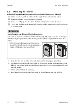
Page 28: ... could be damaged when drilling 2 Align the wall mounting bracket horizontally on the wall and use it to mark the position of the drill holes Use at least one hole on the left hand side and one on the right hand side of the wall mounting bracket 3 Drill the holes and insert the wall plugs 4 Secure the wall mounting bracket horizontally on the wall using screws and washers 5 2 Mounting the Inverter...

Page 29: ...he hole or holes to attach the safety screw and insert the wall plug s Hook the inverter into the wall mounting bracket Mark the drill hole on the left hand side or right hand side If you want to secure the inverter with two safety screws mark both drill holes Remove the inverter by lifting it up vertically and out of the wall mounting bracket 6 Hook the inverter into the wall mounting bracket ...

Page 30: ...y tighten the screws hand tight That prevents the inverter being lifted out 8 Close the recessed grips with the ventilation grids Ensure the assignment is correct The correct assignment is marked on the inside of each ventilation grid links left for the left hand side and rechts right for the right hand side 9 If the holes for attaching the safety screw are pre drilled secure the inverter with at ...

Page 31: ...ive components can lead to lethal electric shocks Do not touch the DC conductors Do not touch any live components of the inverter Before performing any work on the inverter always disconnect it from all voltage sources as described in this document see section 9 Electrostatic Discharge SiHiw_Vor Berühren erden Touching electronic components can cause damage to or destroy the inverter through elect...

Page 32: ...the bottom of the inverter Item Designation Explanation A Positive DC connector with filler plug For connecting the positive DC cables B Socket For connecting the ESS C Negative DC connector with filler plug For connecting the negative DC cables D Enclosure opening For routing the data cables through E Socket For connecting the SMA Power Balancer F Enclosure opening For routing the AC cable throug...

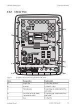
Page 33: ...ts and connection areas in the interior of the inverter Item Designation Explanation A Jumper slot For checking the fans B Terminal For the AC cable C Flat male tabs For earthing the cable shield of the data cable D Screw fixture for the shield connection terminal For earthing the cable shield of the data cable E Fuse For the ESS ...

Page 34: ... method cable bundling ambient temperature and maximum desired line losses for calculation of line losses see design software Sunny Design from software version 2 0 www SMA Solar com Switch disconnector and cable protection WaHiw_Schraubsicherungen als Lasttrenneinrichtung In plants with multiple inverters protect every inverter with a separate miniature circuit breaker Observe the maximum permiss...

Page 35: ...ng the Display Language page 50 The connection requirements of the network operator must be met The mains voltage must be in the permissible range The exact operating range of the inverter is specified in the operating parameters see the Technical Description Operating Parameters at www SMA Solar com 1 Disconnect the miniature circuit breaker and secure against reconnection 2 Loosen all screws and...

Page 36: ...ct N to terminal N Connect L to terminal L 10 Close the inverter and earth the enclosure lid The teeth of the conical spring washers are pushed into the enclosure lid This ensures that the enclosure lid is earthed Attach one conical spring washer to each screw The grooved side of the conical spring washer must point to the screw head Secure the enclosure lid with screws in the sequence 1 to 6 torq...

Page 37: ...otective conductor fails Cable requirement Earthing cable cross section 16 mm at maximum 1 Strip the earthing cable insulation 6 3 3 Additional Earthing of the Enclosure 2 Lead the clamping bracket over the earthing cable Position the protective conductor on the left hand side 3 Screw the clamping bracket tight using the M6x16 cheese head screw and a conical spring washer torque 6 Nm The teeth of ...

Page 38: ...f the PV modules must not exceed 90 of the maximum input voltage of the inverter That prevents the voltage exceeding the maximum input voltage of the inverter at lower ambient temperatures The positive connection cables of the PV modules must be equipped with the positive DC connectors The negative connection cables of the PV modules must be equipped with the negative DC connectors Wichtig_Paralle...

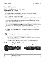
Page 39: ... 12 mm of the cable insulation The clamping bracket clicks audibly into place Electric shock due to high voltages When exposed to sunlight the PV array generates dangerous DC voltage which is present in the DC conductors and the live components of the inverter Touching the DC conductors can result in lethal electric shocks Do not touch the DC conductors 2 Route the stripped cable all the way into ...

Page 40: ...nded wire not visible in the chamber The cable is not correctly in place Remove the cable and go back to step 2 Release the clamping bracket To do so insert a screwdriver blade width 3 5 mm into the clamping bracket and lever it open 4 Push the swivel nut up to the thread and tighten torque 2 Nm 1 2 1 2 ...

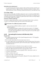
Page 41: ...3 Connecting the PV Array Destruction of the inverter due to overvoltage If the open circuit voltage of the PV modules exceeds the maximum input voltage of the inverter the inverter can be destroyed by the overvoltage If the open circuit voltage of the PV modules exceeds the maximum input voltage of the inverter do not connect any PV strings to the inverter and check the design of the PV plant 2 I...

Page 42: ...ed when all the unused DC inputs are closed with DC connectors and sealing plugs DO NOT insert the sealing plugs DIRECTLY into the DC inputs on the inverter For unused DC connectors push down the clamping bracket and push the swivel nut up to the thread Insert the sealing plug into the DC connector Tighten the DC connector torque 2 Nm Insert the DC connectors with sealing plugs into the correspond...

Page 43: ...YCYv 1 x 2 x 0 25 mm shielded flexible insulated twisted pair 9 Risk of fire due to tightening the screw within the ESS A perfect contact between the ESS and the inverter is only guaranteed if the ESS plug remains flexible Do not tighten the screw in the plug of the ESS 10 Damage to the inverter due to moisture and dust intrusion If the ESS is not plugged in or incorrectly plugged in during operat...

Page 44: ...nverter is not equipped with a SMA Power Balancer plug in system you can order a retrofit kit see section 13 Accessories page 91 The Y cable for the SMA Power Balancer plug in system must be available 1 Disconnect the inverter from all voltage sources see section 9 2 To extend the Y cable Cut the Y cable in the middle Connect the conductors and cable shield 1 1 to the extension cord inside a junct...

Page 45: ...rings to the inverter Install each string fuse as described in this section Requirement A retrofit kit with five fuses and five fuse extractors must be available 1 Disconnect the inverter from all voltage sources see section 9 5 Insert the other two plugs of the Y cable in the respective socket of the other inverters and tighten them 6 6 Installing the String Fuses Damage to the inverter due to st...

Page 46: ...n Manual 6 Electrical Connection SMA Solar Technology AG 5 Commission the inverter see section 8 Commissioning page 51 3 Insert the string fuse into the fuse extractor 4 Insert the fuse extractor with the string fuse into the fuse holder ...

Page 47: ...n of the SMA Power Balancer If the connection is correct and the problem persists contact the SMA Service Line 5 Switch off the miniature circuit breaker of 1 inverter The inverter with the deactivated miniature circuit breaker displays the message Vac Bfr and disconnects from the electricity grid The other two inverters display the message PowerBalance and also disconnect from the electricity gri...

Page 48: ... approve changes of grid relevant parameters The SMA Grid Guard code for changing the grid relevant parameters must be available to apply for an SMA Grid Guard code see the certificate Application for SMA Grid Guard Code at www SMA Solar com 1 Open the user interface of the data logger or software 2 Enter the SMA Grid Guard code in the communication product e g software 3 Select the parameter Defa...

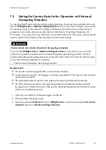
Page 49: ...responsible network operator must approve changes of grid relevant parameters The SMA Grid Guard code for changing the grid relevant parameters must be available to apply for an SMA Grid Guard code see the certificate Application for SMA Grid Guard Code at www SMA Solar com 1 Open the user interface of the data logger or software 2 Enter the SMA Grid Guard code 3 Select the parameter Default and s...

Page 50: ...n the country data set selected 1 Disconnect the inverter from all voltage sources see section 9 2 Select the required language via the two switches 3 Commission the inverter see section 8 Commissioning page 51 7 4 Changing the Display Language Figure 14 Two switches at the bottom of the display assembly Language Switch S2 Switch S1 German B B English B A French A B Spanish A A ...

Page 51: ...t and operating mode of the SMA Power Balancer consecutively After the start up phase has been completed the current power reactive power and displacement power factor cos φ are displayed Have all LEDs gone out The ESS is not plugged in or there is no DC input voltage Plug in the ESS securely or wait until DC input voltage is present Is the green LED flashing The DC input voltage is still too low ...

Page 52: ...ta set and operating mode of the SMA Power Balancer consecutively After the start up phase has been completed the current power reactive power and displacement power factor cos φ are displayed Have all LEDs gone out The ESS is not plugged in or there is no DC input voltage Plug in the ESS securely or wait until DC input voltage is present Is the green LED flashing The DC input voltage is still too...

Page 53: ...connecting the Inverter 2 Remove the ESS 3 Use a current clamp to ensure that no current is present in the DC cables 4 Unlock and remove all DC connectors To do so insert a slotted screwdriver blade width 3 5 mm into one of the side slots and pull the DC connectors straight down DO NOT PULL ON THE CABLE whilst doing this 5 Danger to life due to high voltages The capacitors in the inverter take ten...

Page 54: ...DC inputs of the inverter using a suitable measuring device 7 Unscrew all screws of the enclosure lid and remove the enclosure lid 8 Ensure that no voltage is present between L and N at the AC terminal using a suitable measuring device 9 Ensure that no voltage is present between L and PE at the AC terminal using a suitable measuring device ...

Page 55: ...A Solar Technology AG 9 Disconnecting the Inverter 10 Damage to the inverter due to electrostatic discharge The internal components of the inverter can be irreparably damaged by electrostatic discharge Earth yourself before touching any components ...

Page 56: ...rror or fault message is shown in the display see section 10 2 3 Errors Faults Warnings page 60 Yellow LED Glowing Permanent operation inhibition The specific error or fault message is shown in the display see section 10 2 3 Errors Faults Warnings page 60 Flashing Error or fault The specific error or fault message is shown in the display see section 10 2 3 Errors Faults Warnings page 60 All LEDs a...

Page 57: ...uring operation moisture and dust can penetrate the inverter If the ESS is not correctly plugged in this can cause contacts in the ESS to wear or the ESS might fall out of the socket This can result in yield loss and damage to the ESS Always plug in the ESS as follows Firmly plug in the ESS until it is flush with the enclosure Ensure that the gap between the ESS and the enclosure is no more than 1...

Page 58: ...ing to the electricity grid Error Designation of the current fault or the current error Event Cnt Number of events that have occurred Fac Mains frequency h On Total operating hours h total Total number of operating hours in feed in operation Iac Ist Line current Ipv Direct current Is Apparent current Line conductor The line conductor to which the inverter is connected Netz Ein Total number of grid...

Page 59: ...power output automatically due to the network operator s specifications The Power Reducer Box transfers the signal from the network operator to the inverter via the Sunny WebBox disturbance The inverter has detected a fault The specific message is also displayed see section 10 2 3 Errors Faults Warnings page 60 Earthfault Measurement of the insulation resistance of the PV plant Error The inverter ...

Page 60: ... input voltage of the inverter connect the DC connectors to the inverter again If the DC voltage is above the maximum input voltage of the inverter check the PV plant design or contact installer of the PV array If this message is repeated frequently disconnect the inverter see section 9 and contact the SMA Service Line ACVtgRPro The ten minute average mains voltage is no longer within the permissi...

Page 61: ...the function of the string fuses see section 10 10 Derating The inverter reduces its power output due to overheating Corrective measures Clean the fans The inverter reduces its power output because the DC input current exceeds the maximum input current of the inverter Corrective measures Ensure that the PV plant is designed correctly dI Bfr dI Srr The inverter has detected a change in the differen...

Page 62: ...orrective measures Ensure that the AC cable is correctly connected see section 6 3 2 Connecting the Inverter to the Electricity Grid page 35 Ensure that the mains frequency is in the permissible range If the mains frequency is in the permissible range and this message is still displayed contact the SMA Service Line HW Signal Internal measurement fault or the hardware is defective Corrective measur...

Page 63: ...ID_CLOSE One of the grid relays does not close The inverter checks the relays which connect the inverter to the electricity grid before the inverter feeds in to the electricity grid If the grid relays do not function properly the inverter will not connect to the electricity grid Corrective measures Contact the SMA Service Line REL_INV_OPEN REL_GRID_OPEN One of the grid relays does not open The inv...

Page 64: ...DI converter The inverter has detected an insulation fault on the DC side Corrective measures Ensure that the PV plant is insulated correctly Ensure that there is no earth fault Checking the PV Plant for Earth Faults SD Imax The inverter has detected an overcurrent on the AC side The inverter disconnects from the electricity grid for safety reasons and afterwards tries to reconnect to the grid Cor...

Page 65: ...ers Uac Min and Uac Max If the AC cable is connected correctly the mains voltage is within the permissible range and this message is still displayed contact the SMA Service Line UpvMax Upv Max Overvoltage at DC input The inverter may be destroyed Corrective measures Disconnect the miniature circuit breaker Remove the ESS Unlock and remove all DC connectors To do so insert a slotted screwdriver bla...

Page 66: ...fan guard Clean the fan guard with a soft brush a paint brush a cloth or compressed air UZWK Max UzwkMax The internal hardware monitoring system has detected an overvoltage in the intermediate circuit of the inverter Corrective measures If this message is displayed frequently contact the SMA Service Line Watchdog Watchdog Srr Internal program run fault Corrective measures If this message is displa...

Page 67: ...an guard Remove the fan slowly from the inverter Use a screwdriver to push the two detents at the right hand edge of the fan guard to the right hand side and remove them from the retainer Push the detents of the fan towards the middle of the fan Unlock and remove the fan plug 5 Damage to the fan due to compressed air Clean the fan with a soft brush a paint brush or a damp cloth ...

Page 68: ...oduct to Set the Parameters 1 Open the user interface of the data logger or software 2 Enter the installer password 3 Select the parameter Fan Test and set it to 1 or Fan test and set it to On 4 Check whether air is coming out of the ventilation grids and whether the fans are making any unusual noises If there is no air coming out of the ventilation grids or the fans are making unusual noises then...

Page 69: ...l noises If there is no air coming out of the ventilation grids or the fans are making unusual noises then presumably the fans were not installed properly Check the fan installation If the fans were installed correctly contact the SMA Service Line 5 Disconnect the inverter from all voltage sources see section 9 6 Remove the jumper from the slot 150V at the right hand side next to the display 7 Com...

Page 70: ... ventilation grids towards the side 2 Damage to the inverter due to foreign bodies Do not remove the ventilation grids permanently otherwise foreign bodies could enter into the enclosure 4 Close the recessed grips with the ventilation grids Ensure the assignment is correct Each ventilation grid is assigned to an enclosure side on the inside links left for the left hand side and rechts right for th...

Page 71: ...discolouration or are burnt out or the plastic is damaged That prevents the ESS disconnecting the PV array reliably Order a new ESS and replace the damaged ESS see section 13 Accessories page 91 10 6 Checking the ESS for Wear 1 Remove the ESS The metal mounting tabs and plastic must not be discoloured or damaged 3 Risk of fire due to tightening the screw within the ESS A perfect contact between th...

Page 72: ...t correctly plugged in this can cause contacts in the ESS to wear or the ESS might fall out of the socket This can result in yield loss and damage to the ESS Always plug in the ESS as follows Firmly plug in the ESS until it is flush with the enclosure Ensure that the gap between the ESS and the enclosure is no more than 1 mm 10 7 Checking the PV Plant for Earth Faults Danger to life due to electri...

Page 73: ...ve and negative pole If the following results are present at the same time there is an earth fault in the PV plant All measured voltages are stable The sum of the two voltages against the earth potential is approximately equal to the voltage between the positive and negative poles Determine the location of the earth fault via the ratio of the two measured voltages Eliminate the earth fault If ther...

Page 74: ...tors inside the inverter Item Designation A Left hand connection wire with loop B Middle connection wire C Right hand connection wire Destruction of the inverter due to overvoltage If varistors are missing the inverter is no longer protected against overvoltage Do not operate the inverter without varistors in plants with a high risk of overvoltages Do not recommission the inverter until the defect...

Page 75: ... Solar Technology AG recommends replacing all varistors immediately Order new varistors and insertion tools see section 13 Accessories page 91 If new varistors are available replace all varistors see section 10 9 If a conductive connection is present contact the SMA Service Line 2 Use a multimeter to measure whether there is a conductive connection between the middle connection wire and the right ...

Page 76: ...on tool from the contacts of the connecting terminal plate 6 Commission the inverter see section 8 Commissioning page 51 10 9 Replacing the Varistors 2 Insert the insertion tool into the clamp contacts of the connecting terminal plate 3 Remove the varistor from the connecting terminal plate 4 Insert the new varistor into the terminals For this purpose insert the connection wire with loop into the ...

Page 77: ...ped or be defective Each string fuse is assigned to one string Check the function of each string fuse as described below 1 Disconnect the inverter from all voltage sources see section 9 10 10 Checking the Function of the String Fuses Figure 16 Assignment of the string fuses to the strings 2 Remove the string fuse with the fuse extractor from the fuse holder 3 Remove the string fuse from the fuse e...

Page 78: ...Order a new string fuse see section 13 Accessories page 91 Have all strings with defective string fuses checked by the installer of the PV array Commission the inverter after the strings have been checked see section 8 Commissioning page 51 If new string fuses are available replace all string fuses see section 10 11 4 Use a continuity tester to measure whether the string fuse is conductive ...

Page 79: ...cing the String Fuses Damage to the inverter due to string fuse burn off It cannot be guaranteed that commercially available string fuses will function correctly In the event of an error the string fuses can burn off Install only string fuses available from SMA Solar Technology AG in the inverter 2 Insert a new string fuse in a new fuse extractor 3 Insert the fuse extractor with the string fuse in...

Page 80: ...ancer is connected remove the cable of the SMA Power Balancer 5 Close the inverter The teeth of the conical spring washers are pushed into the enclosure lid This ensures that the enclosure lid is earthed 11 Decommissioning 11 1 Dismounting the Inverter Attach one conical spring washer to each screw The grooved side of the conical spring washer must point to the screw head Secure the enclosure lid ...

Page 81: ...cable disposal regulations for electronic waste or Return the inverter at your own cost to SMA Solar Technology AG see section 14 Contact page 92 Label the package ZUR ENTSORGUNG FOR DISPOSAL 7 Loosen the screws between the inverter and the wall mounting bracket on both sides 8 If the inverter is protected against theft loosen the safety screws 9 Remove the inverter by lifting it up vertically and...

Page 82: ...put voltage The maximum open circuit voltage that can occur at a cell temperature of 10 C must not exceed the maximum input voltage 700 V MPP voltage range 333 V 500 V Rated input voltage 350 V Minimum input voltage 333 V Start input voltage 400 V Maximum input current 28 A Maximum input current per string Maximum permitted current which may flow via one DC connector 28 A Number of independent MPP...

Page 83: ...0 V 37 5 A Maximum output current 40 A Total harmonic factor of the output current with total harmonic factor of the AC voltage 2 and AC power 50 of the rated power 3 Rated power frequency 50 Hz AC power frequency 50 Hz 60 Hz Operating range at AC power frequency 50 Hz 44 Hz 55 Hz Operating range at AC power frequency 60 Hz 54 Hz 65 Hz Displacement power factor adjustable 0 8overexcited 0 8underex...

Page 84: ...The maximum open circuit voltage that can occur with 10 C cell temperature must not exceed the maximum input voltage 700 V MPP voltage range 333 V 500 V Rated input voltage 350 V Minimum input voltage 333 V Initial input voltage 400 V Maximum input current 31 A Maximum input current per string Maximum permitted current allowed through one DC connector 31 A Number of independent MPP inputs 1 String...

Page 85: ... 7 A Maximum output current 44 A Total harmonic factor of the output current with total harmonic factor of the AC voltage 2 and AC power 50 of the rated power 3 Rated mains frequency 50 Hz AC mains frequency 50 Hz 60 Hz Operating range at AC mains frequency 50 Hz 44 Hz 55 Hz Operating range at AC mains frequency 60 Hz 54 Hz 65 Hz Displacement power factor adjustable 0 8overexcited 0 8underexcited ...

Page 86: ...The maximum open circuit voltage that can occur with 10 C cell temperature must not exceed the maximum input voltage 700 V MPP voltage range 333 V 500 V Rated input voltage 350 V Minimum input voltage 333 V Initial input voltage 400 V Maximum input current 34 A Maximum input current per string Maximum permitted current allowed through one DC connector 34 A Number of independent MPP inputs 1 String...

Page 87: ... 8 A Maximum output current 48 A Total harmonic factor of the output current with total harmonic factor of the AC voltage 2 and AC power 50 of the rated power 3 Rated mains frequency 50 Hz AC mains frequency 50 Hz 60 Hz Operating range at AC mains frequency 50 Hz 44 Hz 55 Hz Operating range at AC mains frequency 60 Hz 54 Hz 65 Hz Displacement power factor adjustable 0 8overexcited 0 8underexcited ...

Page 88: ...de the enclosure 2 Operating temperature range 25 C 60 C Maximum permissible value for relative humidity non condensing 100 Maximum operating altitude above MSL 3 000 m Typical noise emission for SMC 9000TLRP 10 42 dB A Typical noise emission for SMC 10000TLRP 10 45 dB A Typical noise emission for SMC 11000TLRP 10 46 dB A Power loss in night mode 0 15 W Topology Transformerless Cooling concept SMA...

Page 89: ...id monitoring SMA Grid Guard 2 1 Maximum permissible fuse protection 80 A Earth fault monitoring Insulation monitoring Riso 280 k Ω All pole sensitive residual current monitoring unit Available 12 4 Approvals Country standard as per 11 2012 SMC 9000TLRP 10 SMC 10000TLRP 10 SMC 11000TLRP 10 VDE 0126 1 1 VDE AR N 4105 UTE C15 712 1 C10 C11 PPDS RD 1663 RD 661 EN 50438 EN 50438 Does not apply to all ...

Page 90: ...witching current 35 A Maximum switching voltage 800 V Maximum PV power 12 kW Degree of protection when plugged in IP65 Degree of protection when removed IP21 Fuse for the ESS F200 600 V 4 A fast acting soldered non replaceable 12 8 Torques Enclosure lid screws 6 0 Nm Additional earth terminal 6 0 Nm Cheese head screw for securing the enclosure to the wall mounting bracket 6 0 Nm SUNCLIX swivel nut...

Page 91: ...WZ Replacement varistors Set with two thermally monitored varistors incl insertion tool MSWR TV 7 Ventilation grid Ventilation grid set right and left as spare part 45 7202 RS485 retrofit kit RS485 interface 485PB SMC NR SMA Power Balancer Y cable Connecting cable for SMA Power Balancer plug in system 2 2 m PBL YCABLE 10 String fuses 8 A Retrofit kit with 5 x 8 A fuses incl fuse protection FUSEKIT...

Page 92: ...r Firmware version of the inverter Special country specific settings of the inverter if applicable Type and number of the PV modules connected Installation location and installation altitude of the inverter LED signal and display message of the inverter Optional equipment e g communication products STSatz_Kontakt_Adresse SMA Solar Technology AG Sonnenallee 1 34266 Niestetal Germany www SMA de SMA ...

Page 93: ...ur device These are also available online at www SMA Solar com and can be downloaded and are available on paper from the usual sales channels if required Trademarks All trademarks are recognised even if these are not marked separately Missing designations do not mean that a product or brand is not a registered trademark The Bluetooth word mark and logos are registered trademarks owned by Bluetooth...

Page 94: ......

Page 95: ......
Page 96: ...ZZZ 60 6RODU FRP 60 6RODU 7HFKQRORJ ...

Reviews: