


3
AION
TM
IQ
1. AION
TM
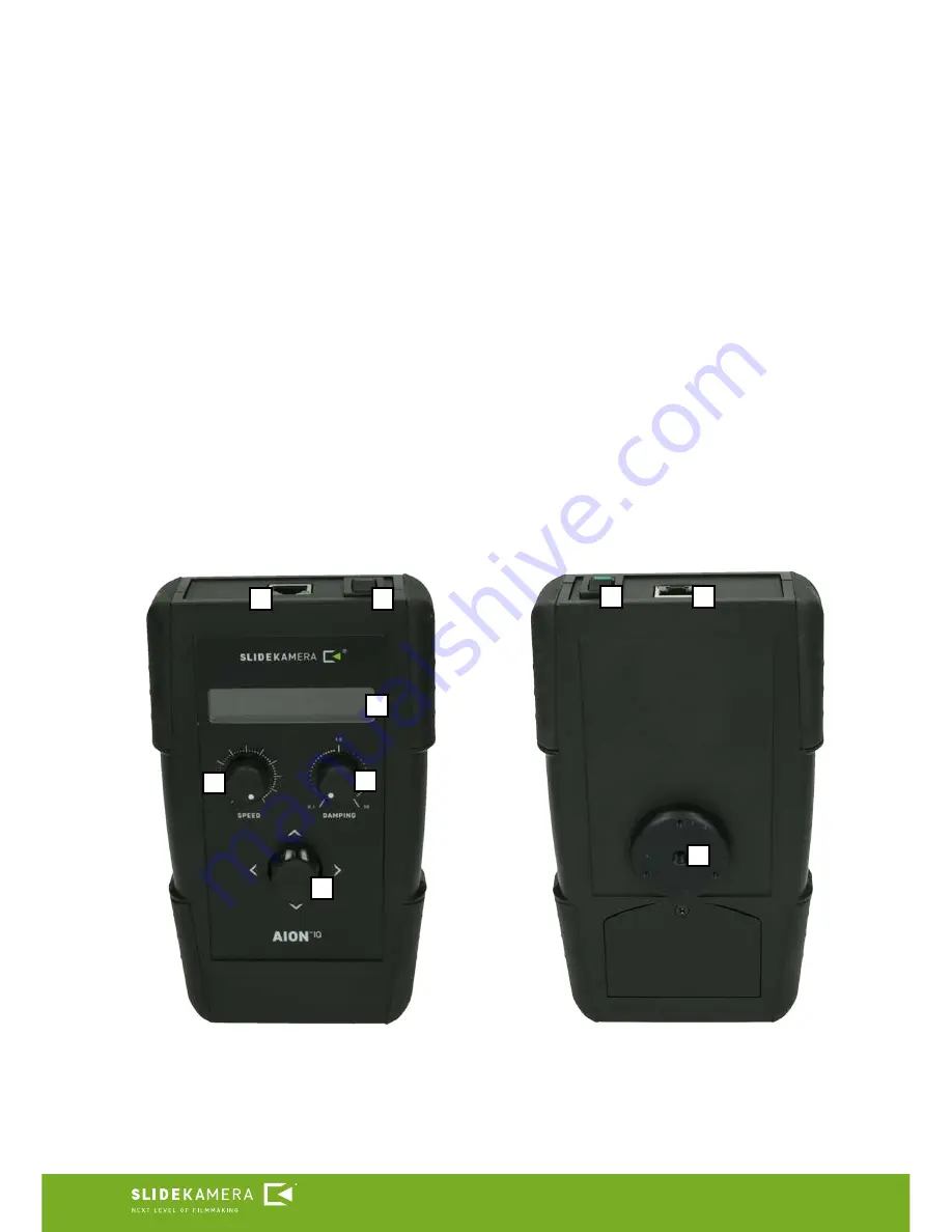
IQ controller
Front panel of the controller is equipped a joystick and two knobs to adjust:
SPEED and DAMPING. SPEED knob allows to adjust speed range, whereas
DAMPING knob regulates smooth acceleration and deceleration of movement,
ie. the user can adjust the time at which the drive reaches the desired speed
or stops. RJ-45 cable socket and power switch are located on the upper wall of
the controller housing. Joystick, placed in the centre of the front panel, enables
user friendly programming, controlling and configuration. Simple and functional
menu provides the ergonomics of operation. AION
TM
IQ controller is equipped
with 1/4” mounting hole that allows to attach it to slider cart, for example, using
Slidekamera VARIO
TM
Magic arm 8” or 11”.
[1]
Power switch
[2]
RJ-45 cable socket
[3]
LCD display
[4]
SPEED knob
[5]
DAMPING knob
[6]
Joystick
[7]
1/4” mounting hole
5
4
6
1
2
2
1
7
3
Summary of Contents for AION IQ
Page 14: ......


