


13
SYSTEM OVER
VIEW
INST
ALLA
TION
ST
ART UP
USER MANUAL
SER
VICE
TECHNICAL
SPECIFICA
TIONS
ON/OFF CONTROL PANELS/INFO PANEL
1. To activate the control station, press both on buttons (2 and 4). The active station indicator (3) will turn on to indicate that the control
station is active.
2. To run the truster(s), you can now move the joystick(s) (1) in the choosen direction. The joysticks will return to center position when
released.
3. To stop the thruster(s) immediately in an emergency situation, press the red emergency stop button (9) on the info panel. The active
emergency stop indicator (7) will turn on to confirm that the emergency stop button is enganged. When this emergency button is enga
-
ged, the hydraulic system will go to safe mode. If more than one info panel are installed, the active emergency stop indicator (7) at the
info panel that was engaged will have a continous red light. The active emergency stop indicator (7) on the other info panel(s) will have
a flashing red light, to indicate that the emergency stop button (9) is engaged somewhere else in the hydraulic system. To deactive the
emergency stop function, make sure to press the emergency stop button (9) on the info panel that has a continous red light on the aci-
tve emergency stop indicator (7), this would be the same info panel that was originally engaged.
5. The hydraulic oil temperature indicator (6) and an audiable alarm will engage in a situation where the hydraulic oil temperature is
above 70°C.
High oil temperature will reduce the lifetime of the oil and in worst case scenario damage hydraulic components.
It is therefore important to find and eliminate the reason for the alarm. The alarm will stay active as long as the temperature is above
70°C. Pressing the red emergency stop button will stop the audible alarm, but the indicator will stay active.
6. The hydraulic oil level indicator (8) and an audiable alarm will engage when the oil level is below recommended minimum level.
Run-
ning the hydraulic pump(s) dry, or with limited available oil flow, can damage the pump(s).
It is therefore important to find and
eliminate the reason for the alarm. The alarm will stay active as long as the oil level is low. Pressing the red emergency stop button will
stop the audible alarm, but the indicator will stay active.
8. To deactive a active control station, press the off button (5). The active station indicator (3) will turn off to indicate that the control
station is not active.
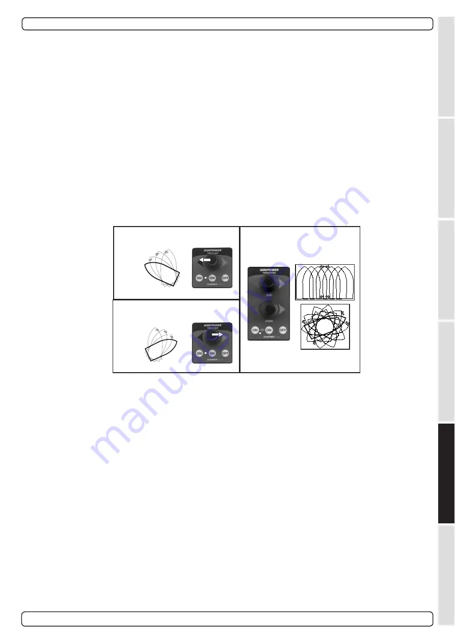
Turn boat to port
Turn boat to starboard
Bow+Stern
Thruster
How to use a bowthruster
1. Please take some time to exercise thruster usage in open water to avoid damages to your boat.
3. Acivate the control panel
4. Move the joystick in the direction you wish the bow to move. Other controls like footswitches or toggle-switches on
the throttle can be used. These are normally logically installed, so by engaging the port control, the bow goes port etc. In case of any
doubts, try in open waters first.
5. Depending on the sideways speed of the bow, you must disengage the control device shortly before the bow is in the
desired direction, as the boat will continue to move after stopping the bowthruster.
How to use a single stern thruster
Some boats might however have installed a single stern thruster because of space limitation in the bow. In this case the stern
thruster is used in the same way as a single bow thruster (see above) for moving the boat’s stern.
How to use a bow and stern thruster combined
The combination of a bow and stern thruster offers total manoeuvrability to the boat and the opportunity to move the bow
and the stern separately from each other. This enables you to move the boat sideways in both directions and to turn the boat
around its own axis staying at the same place.
• Again, if in doubt, try in open water first!
Operating the thruster system
Sidepower Hydraulic System
2.3 - 2006


