


Issue 10 (01/10/2004) Page 247 of 258
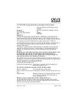
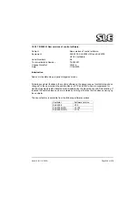
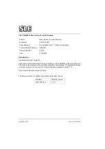
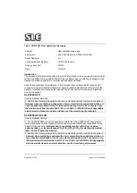
19.1.15 SI 020901 Cleaning, Disinfection and Sterilisation of SLE ventilators.
Subject:
Cleaning, Disinfection and Sterilisation of SLE
ventilators.
Equipment:
SLE 2000, SLE2000 HFO, SLE2000 HFO Plus
Serial Numbers:
All
Service information Number:
SI020901
Date:
24/09/2002
Introduction
The MDA has issued a safety notice SN 2001(28) “Compatibility of medical devices and
reprocessing equipment with Decontamination agents,” which states that manufactures of
medical devices should state decontamination agents that are compatible with there products.
The following is an extract from Medical Devices Agency safety notice SN 2001(28)
The Medical Devices Agency continues to receive reports about damage to medical devices or
their components and to reprocessing equipment following contact with incompatible
decontamination agents.
The damage is usually the result of reactions between the decontamination agent and the
materials of construction of the device or reprocessing unit. Such damage may affect the
performance or functionality of the device or the effectiveness of the decontamination
procedure.
Manufacturers of reusable medical devices are required to provide information on how
to decontaminate their devices. This information should include the types of
decontamination agent that may be used, together with a warning of any agents or
processes that are known to be detrimental to the device.
Due to SN 2001(28) we are issuing more detailed guidelines for the Cleaning, Disinfection and
Sterilisation of our products, to be used in conjunction with those already in the user manuals.
Cleaning, Disinfection and Sterilisation Guidelines.
We recommend the following agents:
Ventilator outer casings and pole: Liquid cleaner or detergent. (As recommended by an
appropriate hospital authority).
Do not use any strong solvent cleaners on the front panels or labels.
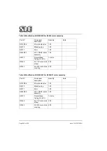
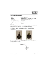
Main and rotating jets:
70% Isopropranol alcohol (AZO wipes).
Do not use Haz Tab on the main and rotating jet or manifold as this may cause corrosion over
time.
Exhalation block:
Standard autoclave at a 134 degrees Celsius for 3 minutes
or at 121 degrees Celsius for 20 minutes. No limit to
number of autoclave cycles
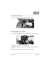
Measures to prevent contamination of SLE ventilators whilst in use.
We recommend that in line bacterial filters are used between the patient circuit and the
exhalation block and the fresh gas port and humidifier supply line.We also recommend that
single use patient circuits are used where possible.
Summary of Contents for 2000 HFO
Page 1: ...Issue 10 SLE 2000 HFO Ventilator Service manual High Frequency Oscillatory Ventilator 0120 ...
Page 8: ...Page 8 of 258 Issue 10 01 10 2004 This page is intentionally blank ...
Page 9: ...Issue 10 01 10 2004 Page 9 of 258 Introduction ...
Page 11: ...Issue 10 01 10 2004 Page 11 of 258 Ventilator Control Description ...
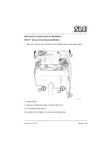
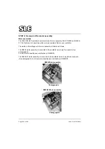
Page 17: ...Issue 10 01 10 2004 Page 17 of 258 Access to Internal Components ...
Page 26: ...Page 26 of 258 Issue 10 01 10 2004 This page is intentionally blank ...
Page 27: ...Issue 10 01 10 2004 Page 27 of 258 Maintenance ...
Page 35: ...Issue 10 01 10 2004 Page 35 of 258 Overhual ...
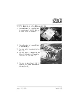
Page 37: ...Issue 10 01 10 2004 Page 37 of 258 Exchanging a Pneumatic Unit ...
Page 39: ...Issue 10 01 10 2004 Page 39 of 258 Setup and Calibration ...
Page 57: ...Issue 10 01 10 2004 Page 57 of 258 Technical Specification ...
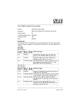
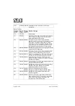
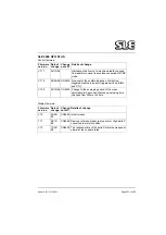
Page 73: ...Issue 10 01 10 2004 Page 73 of 258 Troubleshooting Chart ...
Page 78: ...Page 78 of 258 Issue 10 01 10 2004 This page is intentionally blank ...
Page 79: ...Issue 10 01 10 2004 Page 79 of 258 Circuit Details ...
Page 80: ...Page 80 of 258 Issue 10 01 10 2004 17 Circuit Details 17 1 AS A0700 02 Display Board Assembly ...
Page 81: ...Issue 10 01 10 2004 Page 81 of 258 17 1 1 CD A0700 02 Display Board Circuit Diagram ...
Page 83: ...Issue 10 01 10 2004 Page 83 of 258 17 2 AS A0701 02 LED PCB Assembly ...
Page 84: ...Page 84 of 258 Issue 10 01 10 2004 17 2 1 CD A0701 02 LED Board Circuit Diagram ...
Page 87: ...Issue 10 01 10 2004 Page 87 of 258 17 3 AS A0702 04 CPU PCB Issue 2 Sheet 1 of 2 ...
Page 88: ...Page 88 of 258 Issue 10 01 10 2004 17 3 1 AS A0702 04 CPU PCB Issue 1 Sheet 2 of 2 ...
Page 93: ...Issue 10 01 10 2004 Page 93 of 258 17 4 AS A0702 04 CPU PCB Issue 3 Sheet 1 of 2 ...
Page 94: ...Page 94 of 258 Issue 10 01 10 2004 17 4 1 AS A0702 04 CPU PCB Issue 3 Sheet 2 of 2 ...
Page 99: ...Issue 10 01 10 2004 Page 99 of 258 17 5 AS A0702 04 CPU PCB Issue 5 Sheet 1 of 2 ...
Page 100: ...Page 100 of 258 Issue 10 01 10 2004 17 5 1 AS A0702 04 CPU PCB Issue 5 Sheet 2 of 2 ...
Page 126: ...Page 126 of 258 Issue 10 01 10 2004 17 10 AS A0737 01 Bargraph Display PCB Assembly ...
Page 127: ...Issue 10 01 10 2004 Page 127 of 258 17 10 1 CD A0737 01 Bargraph Display PCB Circuit Diagram ...
Page 129: ...Issue 10 01 10 2004 Page 129 of 258 17 11 AS A0738 02 Alarm PCB Assembly ...
Page 130: ...Page 130 of 258 Issue 10 01 10 2004 17 11 1 CD A0738 02 Alarm PCB Circuit Diagram ...
Page 139: ...Issue 10 01 10 2004 Page 139 of 258 17 13 AS A0739 02 Motor Drive PCB Issue 3 Revision C ...
Page 143: ...Issue 10 01 10 2004 Page 143 of 258 17 14 AS A0756 HFO Motor Start Up PCB Issue 2 ...
Page 145: ...Issue 10 01 10 2004 Page 145 of 258 17 15 AS A0745 Pressure Drift Monitor Board Issue 1 ...
Page 147: ...Issue 10 01 10 2004 Page 147 of 258 17 16 AS A0745 Pressure Drift Monitor Board Issue 2 ...
Page 150: ...Page 150 of 258 Issue 10 01 10 2004 17 17 Serial Interface Option CD A0702 03 ...
Page 153: ...Issue 10 01 10 2004 Page 153 of 258 17 19 Front Panel ...
Page 154: ...Page 154 of 258 Issue 10 01 10 2004 17 20 SK0057 Power Supply Wiring Diagram ...
Page 156: ...Page 156 of 258 Issue 10 01 10 2004 17 22 Electronic Chassis Sheet 1 of 2 ...
Page 157: ...Issue 10 01 10 2004 Page 157 of 258 17 22 1 Electronic Chassis Sheet 2 of 2 ...
Page 186: ...Page 186 of 258 Issue 10 01 10 2004 This page is intentionally blank ...
Page 189: ...Page 189 of 258 CD A0702 04 Issue 2 ...
Page 190: ...Page 190 of 258 ...
Page 191: ...Page 191 of 258 CD A0702 04 Issue 3 ...
Page 192: ...Page 192 of 258 ...
Page 193: ...Page 193 of 258 CD A0702 04 Issue 4 ...
Page 194: ...Page 194 of 258 ...
Page 195: ...Page 195 of 258 CD A0736 03 Issue 2 Note Please check the revision status of the main board ...
Page 196: ...Page 196 of 258 ...
Page 197: ...Page 197 of 258 CD A0736 03 issue 3 Note Please check the revision status of the main board ...
Page 198: ...Page 198 of 258 ...
Page 199: ...Page 199 of 258 CD A0736 03 issue 4 Note Please check the revision status of the main board ...
Page 200: ...Page 200 of 258 ...
Page 201: ...Page 201 of 258 CD A0736 03 issue 5 Note Please check the revision status of the main board ...
Page 202: ...Page 202 of 258 ...
Page 203: ...Page 203 of 258 CD W0308 ...
Page 204: ...Page 204 of 258 ...
Page 205: ...Issue 10 01 10 2004 Page 205 of 258 Service Information and Technical Bulletins ...
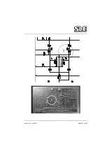
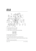
Page 221: ...Issue 10 01 10 2004 Page 221 of 258 The pneumatic circuit diagram is shown here ...
Page 228: ...Page 228 of 258 Issue 10 01 10 2004 Figure 4b ...
Page 231: ...Issue 10 01 10 2004 Page 231 of 258 ...
Page 237: ...Issue 10 01 10 2004 Page 237 of 258 100nf ...
Page 258: ......


