


Issue 10 (01/10/2004) Page 137 of 258
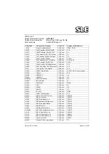
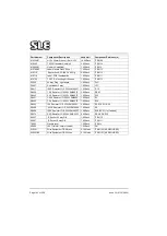
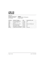
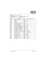
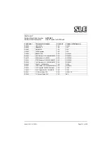
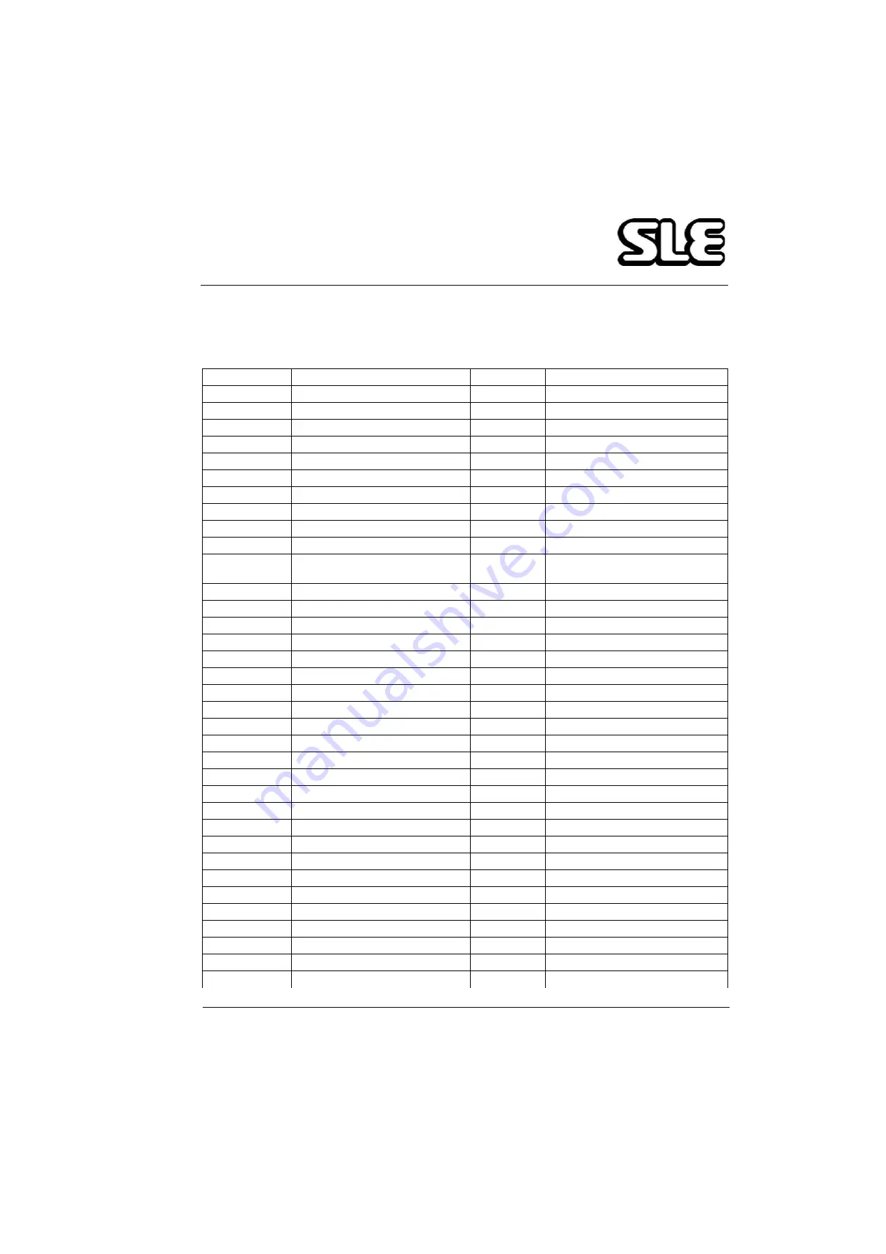
PARTS LIST
Finished Item Stock Number
A0739/02
Finished Item Description
Motor Drive PCB Assy' CE Mk
Bill of materials
AS/A0739/02 Issue 1
Part Number
Component Description
Used Unit
Component Reference(s)
J0739
Motor Drive Board blank
1.00 Each
ITEM 1 (PCB)
C0410
3.3nF Capacitor 50V 10% Ceramc
1.00 Each
C1
C0433
1uF Capacitor 35V 20% Tantalum
1.00 Each
C2
C0450
0.1uF Capacitor 63V 10% MKS2
4.00 Each
C3,5,6 & C9
C0469
10uF Capacitor 35V 20% Tant.
2.00 Each
C8,C11
C0260
10nF Capacitor 63V 20% MKS2
1.00 Each
C10
C0277
100uF Capacitor 50 or 63V 20%
1.00 Each
C4
C0436
22uF Capacitor 35V 20%
2.00 Each
C7,C12
D0623
BAX16 Diode
1.00 Each
D1
D0624
5401 Diode
8.00 Each
D2-D9
D0402
1N4007 Plastic Diode
3.00 Each
D10,D11 & D12 Added on rear as
modification
D0636
IRLU110
1.00 Each
MOS1
D0625
L297
1.00 Each
U1
D0626
L298N
1.00 Each
U2
D0627
RC4152
1.00 Each
U3
D0428
LM7812CT
1.00 Each
U4
D0432
LM7805CT
1.00 Each
U5
D0601/01
CXA-L1OL Inverter
1.00 Each
U6
V0405
10K Trimmer, cermet, top adj
1.00 Each
RV1
R0451
3.92K Resistor 1% 0.25W SMA020
1.00 Each
R1
R0469
22.1K Resistor 1% 0.25W SMA020 1.00 Each
R2
R0463
10K Resistor 1% 0.25W SMA0207
4.00 Each
R3,R14,R17,R20
R0574
2.0R Resistor 1% 0.25W SMA0207
8.00 Each
R4,5,8,R9-R13
R0436
1.0K Resistor 1% 0.25W SMA0207
2.00 Each
R6,R7
R0443
2.2K Resistor 1% 0.25W SMA0207
1.00 Each
R15
R0460
7.5K Resistor 1% 0.25W SMA0207
1.00 Each
R16
R0417
180R Resistor 1% 0.25W SMA0207
1.00 Each
R18
R0486
100K Resistor 1% 0.25W SMA0207 1.00 Each
R19
P0467
Pcb Header 2 way
1.00 Each
JP1
P0230
64 way Plug - right angle
1.00 Each
PLC
M0680/01
Heatsink (modified)
1.00 Each
ITEM 2
M0228
Heat Sink TO-220
1.00 Each
ITEM 3
M0307
Terminal Pin(Pcb single sided)
1.00 Each
TP1
M0309/01
H12 x 20mm Sleeve (1.2mm I/D)
16.00 Each
ITEM 90
M0463
T0220 Transistor Heatsink
2.00 Each
ITEM 14
Summary of Contents for 2000 HFO
Page 1: ...Issue 10 SLE 2000 HFO Ventilator Service manual High Frequency Oscillatory Ventilator 0120 ...
Page 8: ...Page 8 of 258 Issue 10 01 10 2004 This page is intentionally blank ...
Page 9: ...Issue 10 01 10 2004 Page 9 of 258 Introduction ...
Page 11: ...Issue 10 01 10 2004 Page 11 of 258 Ventilator Control Description ...
Page 17: ...Issue 10 01 10 2004 Page 17 of 258 Access to Internal Components ...
Page 26: ...Page 26 of 258 Issue 10 01 10 2004 This page is intentionally blank ...
Page 27: ...Issue 10 01 10 2004 Page 27 of 258 Maintenance ...
Page 35: ...Issue 10 01 10 2004 Page 35 of 258 Overhual ...
Page 37: ...Issue 10 01 10 2004 Page 37 of 258 Exchanging a Pneumatic Unit ...
Page 39: ...Issue 10 01 10 2004 Page 39 of 258 Setup and Calibration ...
Page 57: ...Issue 10 01 10 2004 Page 57 of 258 Technical Specification ...
Page 73: ...Issue 10 01 10 2004 Page 73 of 258 Troubleshooting Chart ...
Page 78: ...Page 78 of 258 Issue 10 01 10 2004 This page is intentionally blank ...
Page 79: ...Issue 10 01 10 2004 Page 79 of 258 Circuit Details ...
Page 80: ...Page 80 of 258 Issue 10 01 10 2004 17 Circuit Details 17 1 AS A0700 02 Display Board Assembly ...
Page 81: ...Issue 10 01 10 2004 Page 81 of 258 17 1 1 CD A0700 02 Display Board Circuit Diagram ...
Page 83: ...Issue 10 01 10 2004 Page 83 of 258 17 2 AS A0701 02 LED PCB Assembly ...
Page 84: ...Page 84 of 258 Issue 10 01 10 2004 17 2 1 CD A0701 02 LED Board Circuit Diagram ...
Page 87: ...Issue 10 01 10 2004 Page 87 of 258 17 3 AS A0702 04 CPU PCB Issue 2 Sheet 1 of 2 ...
Page 88: ...Page 88 of 258 Issue 10 01 10 2004 17 3 1 AS A0702 04 CPU PCB Issue 1 Sheet 2 of 2 ...
Page 93: ...Issue 10 01 10 2004 Page 93 of 258 17 4 AS A0702 04 CPU PCB Issue 3 Sheet 1 of 2 ...
Page 94: ...Page 94 of 258 Issue 10 01 10 2004 17 4 1 AS A0702 04 CPU PCB Issue 3 Sheet 2 of 2 ...
Page 99: ...Issue 10 01 10 2004 Page 99 of 258 17 5 AS A0702 04 CPU PCB Issue 5 Sheet 1 of 2 ...
Page 100: ...Page 100 of 258 Issue 10 01 10 2004 17 5 1 AS A0702 04 CPU PCB Issue 5 Sheet 2 of 2 ...
Page 126: ...Page 126 of 258 Issue 10 01 10 2004 17 10 AS A0737 01 Bargraph Display PCB Assembly ...
Page 127: ...Issue 10 01 10 2004 Page 127 of 258 17 10 1 CD A0737 01 Bargraph Display PCB Circuit Diagram ...
Page 129: ...Issue 10 01 10 2004 Page 129 of 258 17 11 AS A0738 02 Alarm PCB Assembly ...
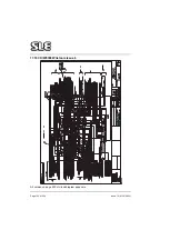
Page 130: ...Page 130 of 258 Issue 10 01 10 2004 17 11 1 CD A0738 02 Alarm PCB Circuit Diagram ...
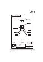
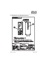
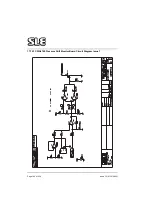
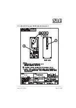
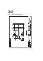
Page 139: ...Issue 10 01 10 2004 Page 139 of 258 17 13 AS A0739 02 Motor Drive PCB Issue 3 Revision C ...
Page 143: ...Issue 10 01 10 2004 Page 143 of 258 17 14 AS A0756 HFO Motor Start Up PCB Issue 2 ...
Page 145: ...Issue 10 01 10 2004 Page 145 of 258 17 15 AS A0745 Pressure Drift Monitor Board Issue 1 ...
Page 147: ...Issue 10 01 10 2004 Page 147 of 258 17 16 AS A0745 Pressure Drift Monitor Board Issue 2 ...
Page 150: ...Page 150 of 258 Issue 10 01 10 2004 17 17 Serial Interface Option CD A0702 03 ...
Page 153: ...Issue 10 01 10 2004 Page 153 of 258 17 19 Front Panel ...
Page 154: ...Page 154 of 258 Issue 10 01 10 2004 17 20 SK0057 Power Supply Wiring Diagram ...
Page 156: ...Page 156 of 258 Issue 10 01 10 2004 17 22 Electronic Chassis Sheet 1 of 2 ...
Page 157: ...Issue 10 01 10 2004 Page 157 of 258 17 22 1 Electronic Chassis Sheet 2 of 2 ...
Page 186: ...Page 186 of 258 Issue 10 01 10 2004 This page is intentionally blank ...
Page 189: ...Page 189 of 258 CD A0702 04 Issue 2 ...
Page 190: ...Page 190 of 258 ...
Page 191: ...Page 191 of 258 CD A0702 04 Issue 3 ...
Page 192: ...Page 192 of 258 ...
Page 193: ...Page 193 of 258 CD A0702 04 Issue 4 ...
Page 194: ...Page 194 of 258 ...
Page 195: ...Page 195 of 258 CD A0736 03 Issue 2 Note Please check the revision status of the main board ...
Page 196: ...Page 196 of 258 ...
Page 197: ...Page 197 of 258 CD A0736 03 issue 3 Note Please check the revision status of the main board ...
Page 198: ...Page 198 of 258 ...
Page 199: ...Page 199 of 258 CD A0736 03 issue 4 Note Please check the revision status of the main board ...
Page 200: ...Page 200 of 258 ...
Page 201: ...Page 201 of 258 CD A0736 03 issue 5 Note Please check the revision status of the main board ...
Page 202: ...Page 202 of 258 ...
Page 203: ...Page 203 of 258 CD W0308 ...
Page 204: ...Page 204 of 258 ...
Page 205: ...Issue 10 01 10 2004 Page 205 of 258 Service Information and Technical Bulletins ...
Page 221: ...Issue 10 01 10 2004 Page 221 of 258 The pneumatic circuit diagram is shown here ...
Page 228: ...Page 228 of 258 Issue 10 01 10 2004 Figure 4b ...
Page 231: ...Issue 10 01 10 2004 Page 231 of 258 ...
Page 237: ...Issue 10 01 10 2004 Page 237 of 258 100nf ...
Page 258: ......