background image

 SKY497 Pilot’s Guide

4-1

Principles of

Operation

C h a p t e r   4

Introduction

This chapter describes 

T

raffic 

A

dvisory (

TA

) criteria and other

factors that affect the display of traffic symbols. Table 

4-1

summarizes the criteria necessary for the 

SKY497

 to display a 

TA

.

Sensitivity Level A

Sensitivity Level B

The SKY497 Will Issue a Traffic Advisory…

No.

If Your

Aircraft…

And Your
Aircraft’s

Altitude Is…

And Your

Landing

Gear Is…

And An Intruder

Aircraft Is Detected…

1 has a radio

altimeter*

below 2000 ft

AGL

within a 0.2 nmi horizontal
radius and a ±600 ft relative
altitude

2

within 15–20 sec. of

CPA**

3

above 2000 ft

AGL

within a 0.55 nmi
horizontal radius and a
±800 ft relative altitude

4

within 20–30 sec. of

CPA**

5 does not

have a radio
altimeter*

down

within a 0.2 nmi horizontal
radius and a ±600 ft relative
altitude

6

within 15–20 sec. of

CPA**

7

up

within a 0.55 nmi
horizontal radius and a
±800 ft relative altitude

8

within 20–30 sec. of

CPA**

9

fixed

within a 0.55 nmi
horizontal radius and a
±800 ft relative altitude

10

within 20–30 sec. of

CPA**

Table 4-1. Ten Situations in Which a TA Will Occur

* Having a radio altimeter means having a compatible radio altimeter wired to the

SKY497

 and providing valid altitude information.

**

CPA

 means 

C

losest 

P

oint of 

A

pproach.

Summary of Contents for SKY497

Page 1: ...Traffic Advisory System Model SKY497 Pilot s Guide for the ...

Page 2: ...nformation about the operation of the SKY497 This guide does not cover all possible interconnec tions with all possible types and numbers of alternate displays and customer supplied switches Refer to your aircraft flight manual and flight manual supplement for information specific to your aircraft If there is conflicting information between those manuals and this pilot s guide your aircraft flight...

Page 3: ...dhereinhavebeendevelopedsolelyoncompanyfundsofL 3 Communications Avionics Systems Inc No government or other contractual support or relationship what soever has existed which in any way affects or mitigates proprietary rights of L 3 Communications Avionics Systems Inc inthesedevelopments MethodsandapparatusdisclosedhereinmaybesubjecttoU S Patents existingorappliedfor L 3CommunicationsAvionicsSyste...

Page 4: ... need to buy another display if you already own a WX 1000 display part number 78 8060 5900 8 The SKY497 can also display its traffic information on a growing number of multi function displays from companies such as Avidyne UPSAT L 3 i linc MFD Garmin and Collins You can even display SKYWATCH traffic information on a compatible weather radar indicator via the L 3 Avionics Systems Radar Graphics Com...

Page 5: ...on System ATCRBS transponder The SKY497 does not track intruder aircraft approaching at a closure rate greater than 900 knots Some traffic within the chosen display range may not be displayed due to traffic prioritizing antenna shielding ground intruder filtering or surveillance range being shorter than the chosen display range Optimum SKY497 performance is realized when intruder aircraft are repo...

Page 6: ...e 6 2 Revision D of the pilot s guide made the following changes Changes occurences of Goodrich Avionics Systems to L 3 Communications Avionics Systems Inc or just L 3 Avionics Systems and makes related company contact information changes On March 28 2003 Goodrich Corporation sold its Avionics Systems division to L 3 Communications Corporation iv SKY497 Pilot s Guide ...

Page 7: ...ontrols Indicators Symbols 2 1 Controls Required for the Stormscope Option 2 6 Control Panel for an Alternate Display not supplied 2 7 Aural Announcements 2 7 Chapter 3 Operating Instructions 3 1 Introduction 3 1 Turn On the SKY497 3 1 Run the Operator Initiated Self Test 3 3 Switch Between Standby Operating Mode 3 3 Change the Display Range 3 4 Change the Vertical Display Mode 3 5 Switch Between ...

Page 8: ...ation 4 1 Introduction 4 1 Sensitivity Levels 4 2 Sensitivity Level A 4 2 Sensitivity Level B 4 2 Audio Inhibit SKY497 4 4 Audio Inhibit GPWS EGPWS or TAWS 4 5 TA Symbol Duration 4 5 Ground Intruder Filtering 4 5 Chapter 5 Display Interpretation 5 1 Introduction 5 1 Chapter 6 Specifications 6 1 ...

Page 9: ... 3 1 Startup Screen 3 1 3 2 Standby Screen 3 2 3 3 In Flight Traffic Screen 3 2 3 4 Failed Screen 3 2 3 5 Test Screen 3 3 3 6 Traffic Screen on the Ground 3 4 3 7 Display Ranges 3 4 4 1 TA Zones If Your Aircraft Has a Radio Altimeter 4 3 4 2 TA Zones If Your Aircraft Has No Radio Altimeter But Does Have a Retractable Landing Gear 4 3 4 3 TA Zones If Your Aircraft Has No Radio Altimeter and a Fixed...

Page 10: ...uations in Which aTA Will Occur 4 1 6 1 TRC497 Specifications 6 1 6 2 WX 1000 SKY497 Display Specifications 6 3 6 3 Directional Antenna Specifications 6 4 Table Title Page List of Tables viii SKY497 Pilot s Guide ...

Page 11: ... EGPWS Enhanced Ground Proximity Warning System FAA Federal Aviation Administration fpm Feet Per Minute FSAW Flight Standards Information Bulletin for Airworthiness GPWS Ground Proximity Warning System IVSI Instantaneous Vertical Speed Indicator MFD Multi Function Display Mod Modification nm Nautical Miles on the display nmi Nautical Miles in the text NRM Normal OPR Operate OT Other Traffic PA Pro...

Page 12: ...andby STC Supplemental Type Certificate TA Traffic Advisory TAS Traffic Advisory System TAWS Terrain Awareness and Warning System TCAS Traffic Alert and Collision Avoidance System TRC Transmitter Receiver Computer TSO Technical Standard Order x SKY497 Pilot s Guide ...

Page 13: ...sion threat The SKY497 displays traffic information on one or more displays The traffic information generally includes the range relative bearing and relative altitude of intruder aircraft The SKY497 also makes aural announcements such as traffic adviso ries on the cockpit audio system The SKY497 is intended for use by corporate and general aviation aircraft including rotor craft Figure 1 1 shows ...

Page 14: ...ning intruders being tracked The TRC also contains Built In Test Equipment BITE which detects faults and verifies proper operation Directional Antenna The directional antenna transmits omnidirectional mode C interrogations and receives directional replies from other transponder equipped aircraft in the vicinity Displays The SKY497 displays traffic information on a WX 1000 SKY497 display and or on ...

Page 15: ...he display ranges for the WX 1000 SKY497 display are 2 6 nmi Alternate Displays Alternate displays include Multi Function Displays MFDs and Electronic Flight Instrument System EFIS displays from companies such as Avidyne Garmin UPSAT L 3 i linc MFD and Collins select Instantaneous Vertical Speed Indica tors IVSIs from Honeywell or Sextant and a compatible weather radar indicator via the L 3 Radar ...

Page 16: ...o each other and to other aircraft systems Notes on Figure 1 5 1 The optional radio altitude input affects the SKY497 audio inhibit feature the ground intruder filtering feature and the sensitivity levels feature See chapter 4 for details 2 A flight data computer or other ARINC 429 output device may replace individual analog sensors for supplying baromet ric altitude and or heading 3 The SKY497 wo...

Page 17: ...PWS TAWS Optional Data Recorder Optional ARINC 429 Radio Altitude SKYWATCH Stormscope Mode Selection SKYWATCH or Display Stormscope Stormscope Display TRC On Off Control When WX 1000 is Powered Down or Removed Override Norm WX 1000 On Off Control TRC On Off Control Display Power TRC SKYWATCH or Control Stormscope Stormscope Control On Off Control with Option Stormscope On Off Control Stormscope Op...

Page 18: ...und your aircraft and the traffic symbols that appear on the display when intruding aircraft enter one of those zones A solid circle is the visual part of the Traffic Advisory TA that the SKY497 generates when it predicts that an intruder aircraft may pose a collision threat The aural part of the TA traffic traffic is annunciated over a cockpit speaker or headset A solid diamond Proximity Advisory...

Page 19: ... ft 1200 ft 600 ft 600 ft up to 11 nmi Sensitivity Level A Look Down BLW Look Up ABV Normal NRM 0 ft 20 seconds for non altitude reporting intruder aircraft Refer to chapter 4 for details CPA Closest Point of Approach 4 nmi Traffic Advisory TA Other Traffic OT Proximity Advisory PA on alternate displays only not including the RGC radar indicator These vertical display mode numbers apply to the WX ...

Page 20: ...rtical display modes normal 2 700 ft look up 9 000 ft to 2 700 ft and look down 2 700 ft to 9 000 ft details on page 6 2 Generates visual and aural advisories of aircraft that may pose a collision threat Performs automatic and operator initiated self tests Offers a high resolution green monochrome CRT display option Transmits interrogations from the ground if desired as well as from the air Shares...

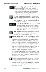
Page 21: ...Indicators Symbols Figures 2 1 and 2 2 and the following paragraphs describe the SKY497 controls indicators and symbols Figure 2 1 Controls Screen Elements in Standby Power Brightness Control Knob OFF BRT This knob controls power to the SKY497 and WX 1000 if installed and adjusts display brightness BRT OFF Power Brightness Control Knob Standby Indicator Test Button Label for Test Button Operating ...

Page 22: ...for altitude reporting aircraft Non altitude reporting aircraft are consid ered to be at the same altitude as your aircraft Traffic Advisory TA A TA consists of a symbol on screen and a traffic traffic message on the cockpit speakers or headset When an intruder aircraft that meets the TA criteria described in chapter 4 is within the displayed range inside or outside of the selected vertical displa...

Page 23: ... into operating mode Label for Operating Mode Button This on screen label identifies the function of the adjacent button The STB label appears on the traffic screen and means go to standby The OPR label appears on the standby screen and means go to operating mode If your aircraft has a squat switch the STB label only appears when your aircraft is on the ground Display Range Button Pressing this bu...

Page 24: ...ing this button in operating mode has no effect Other Traffic OT On the WX 1000 SKY497 display and on the RGC radar indicator this symbol represents an intruder aircraft that has been detected within the selected display range and vertical display mode but which has not generated a TA On alternate displays not including the RGC radar indicator this symbol repre sents an intruder aircraft that has ...

Page 25: ... nmi from your aircraft and the inner range ring represents a distance of 2 nmi Figure 3 7 on page 3 4 shows the range ring arrangements for other display ranges Standby Indicator This indicator is displayed as long as the SKY497 is in standby except when the test screen is displayed during an operator initiated self test In standby the SKY497 does not interrogate process or display traffic Standb...

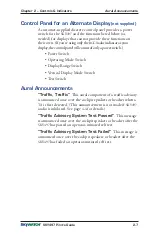
Page 26: ... On some displays when an active TA is detected the background color of the TA ONLY indicator changes from white to amber Controls Required for the Stormscope Option SKYWATCH Stormscope Mode Switch not supplied This panel mounted toggle switch determines whether traffic information or thunderstorm information is displayed The SKY497 and the WX 1000 continue tracking even if the switch is in the ot...

Page 27: ...g Mode Switch Display Range Switch Vertical Display Mode Switch Test Switch Aural Announcements Traffic Traffic This aural component of a traffic advisory is announced once over the cockpit speakers or headset when a TA is first detected This announcement is not made if SKY497 audio is inhibited See page 4 4 for details Traffic Advisory System Test Passed This message is announced once over the co...

Page 28: ......

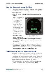
Page 29: ...play brightness A startup screen similar to figure 3 1 appears and stays on the display until the power on self test is complete The L 3 logo will replace the existing BFGoodrich logo sometime after the corporate transition is complete If the SKY497 passes the test and your aircraft has a squat switch and your aircraft is on the ground the standby screen appears figure 3 2 If the SKY497 passes the...

Page 30: ...witch into operating mode the SKY497 only waits 2 seconds for the sensor inputs before it displays the failed screen If a failed screen similar to figure 3 4 appears refer to the Failure Response section on page 3 7 For installations with an ARINC 429 barometric altitude input turning on the SKY497 during flight causes a temporary Error 20 message while the system is syncing up to the 429 data sou...

Page 31: ...led screen push the TEST button again If it fails again refer to the Failure Response section on page 3 7 3 If you hear Traffic advisory system test passed without seeing the test screen and the OFF BRT knob is turned to BRT turn off the SKY497 and contact your authorized L 3 Avionics Systems dealer for troubleshooting help Switch Between Standby Operating Mode When you re on the ground you must m...

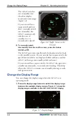
Page 32: ...e STB button label is not displayed while airborne and the SKY497 will not go into standby while airborne If your aircraft has a squat switch the SKY497 also goes into standby automatically 24 seconds after landing This delay allows the SKY497 to remain out of standby during a touch and go maneuver Change the Display Range You can change the display range when the SKY497 is in operating mode 1 Pre...

Page 33: ...rtical surveillance range 10 000 ft regardless of the vertical display mode selected Switch Between SKYWATCH Stormscope If you have a Stormscope WX 1000 installed with the SKY497 you can switch between SKYWATCH and Stormscope screens figures 1 2 and 1 3 using the remote SKYWATCH Stormscope mode switch Once in Stormscope mode you can use the buttons on the display bezel to control Stormscope functi...

Page 34: ...s realized when intruder aircraft are reporting their altitude via a mode C or other altitude reporting transponder Monitor the activity of any traffic displayed Keep in mind the following points when watching traffic on the display Traffic Prioritizing The SKY497 tracks up to 30 intruder aircraft simultaneously but to reduce clutter it displays only the 8 most threatening aircraft of those tracke...

Page 35: ...nce personnel must install a jumper plug if you want to continue using the WX 1000 Operate the SKY497 Without the WX 1000 After removing the WX 1000 for maintenance maintenance personnel will move the WX 1000 maintenance switch to the OVERRIDE WX 1000 maintenance position to allow continued operation of the SKY497 Failure Response All errors indicated by a SKY497 Failed screen figure 3 4 prevent c...

Page 36: ... 1000 skip to step 4 3 If the SKYWATCH Stormscope mode switch is in the Stormscope position switch it into the SKYWATCH position 4 Press the TEST button The resulting self test may provide another error code to write down 5 Remove power from the SKY497 at the circuit breaker If you have a WX 1000 Stormscope the display automatically switches into Stormscope mode once you disconnect power from the ...

Page 37: ...ontal radius and a 600 ft relative altitude 2 within 15 20 sec of CPA 3 above 2000 ft AGL within a 0 55 nmi horizontal radius and a 800 ft relative altitude 4 within 20 30 sec of CPA 5 does not have a radio altimeter down within a 0 2 nmi horizontal radius and a 600 ft relative altitude 6 within 15 20 sec of CPA 7 up within a 0 55 nmi horizontal radius and a 800 ft relative altitude 8 within 20 30...

Page 38: ...ntercept your aircraft within 15 or 20 seconds within 15 seconds for a non altitude reporting intruder aircraft within 20 seconds for an altitude reporting intruder aircraft The SKY497 uses sensitivity level A in the following situations corresponds to numbers 1 2 5 and 6 in table 4 1 1 Your aircraft has a radio altimeter and is below 2 000 ft AGL 2 Your aircraft has no radio altimeter but its ret...

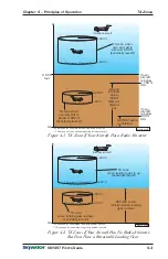
Page 39: ...low 2 000 ft sensitivity level A TA zone when own aircraft is above 2 000 ft sensitivity level B SKY497 audio is inhibited Figure 4 1 TA Zones If Your Aircraft Has a Radio Altimeter Figure 4 2 TA Zones If Your Aircraft Has No Radio Altimeter But Does Have a Retractable Landing Gear 0 2 nmi 600 ft 600 ft This area or 20 seconds 0 55 nmi 800 ft 800 ft This area or 30 seconds 15 seconds for non altit...

Page 40: ...7 This audio inhibit feature prevents the aural part of TAs traffic traffic from being announced during takeoff and landing in order to minimize pilot distraction The correspond ing TA symbols are still displayed The SKY497 uses this audio inhibit feature in the following situations 1 Your aircraft has a radio altimeter and you re below 400 ft AGL See figure 4 1 2 Your aircraft has no radio altime...

Page 41: ... the intruder aircraft no longer meets the TA criteria as long as the SKY497 continues to track the aircraft Ground Intruder Filtering Ground intruder filtering reduces the clutter of visual symbols and aural announcements that would otherwise be generated for intruder aircraft typically present on or near the ground near airports For intruder aircraft determined to be below 380 ft AGL ground intr...

Page 42: ......

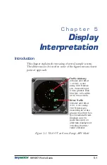
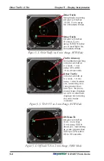
Page 43: ...5 1 TA OT on 6 nmi Range ABV Mode BRT OFF ABV 6nm STB 0 7 03 Traffic Advisory Intruder aircraft at o clock nmi away ft above you descending at a rate greater than fpm within to seconds 1 2 300 500 CPA 20 30 Other Traffic Intruder aircraft at nmi away ft below you ascending at a rate greater than fpm No immediate threat Displays as a solid diamond on alternate displays not including the radar indic...

Page 44: ...Mode BRT OFF Traffic Advisory Non altitude reporting intruder aircraft at o clock nmi away within to seconds 2 1 CPA 15 20 Other Traffic Intruder aircraft at o clock nmi away ft above you ascending at a rate greater than fpm No imme diate threat Displays as a on alternate displays not including the radar indicator 5 1 5 1 000 500 PA RGC BLW 2nm 10 BRT OFF 6nm STB BLW OtherTraffic Non altitude repo...

Page 45: ...ST Figure 5 6 Failed Screen BRT OFF Failed SKY497 Error 2 0 Error 20 Indicates that the barometric input is missing or invalid Once the valid baro metric input returns this screen goes away and normal operation resumes SKY497 Failed Occurs any time the SKY497 detects an error that prohibits further operation of the SKY497 in SKYWATCH mode as long as the message remains on the screen Some alternate...

Page 46: ......

Page 47: ...or rotorcraft installations 10 95 lb 4 97 kg Tracking Capability Up to 30 intruder aircraft displays only the 8 highest priority aircraft Surveillance Range Horizontal tracking radius 11 nmi maximum Relative altitude tracking range 10 000 ft maximum Display Ranges Horizontal display ranges with the WX 1000 SKY497 display 2 and 6 nmi Horizontal display ranges with alternate displays 2 and 6 nmi on ...

Page 48: ... Power Input Requirements 11 to 34 V dc 70 W maximum Transmitter Power Output 40 W peak nominal Operating Temperature 55 to 70 C 67 to 158 F Storage Temperature 55 to 85 C 67 to 185 F Operating Altitude 55 000 ft maximum Cooling Conduction and forced air convection internal fan Certification Compliance U S FAA TSO C147 Contact L 3 Avionics Systems for the latest foreign country certifications Refe...

Page 49: ...igh 3 37 in 8 56 cm wide 8 24 in 20 92 cm deep Weight 2 5 lb 0 2 lbs 1 1 kg 0 1 kg Power Input Requirements 15 15 V dc 0 7 A maximum provided by the TRC497 Operating Temperature 20 to 55 C 4 to 131 F Storage Temperature 55 to 70 C 67 to 158 F Operating Altitude 55 000 ft maximum TSO Compliance C110a and C113 RTCA Compliance DO 160C F1 CA NBM XXXXXXZXXXZUAXXXXXX Specifications subject to change wit...

Page 50: ...an upgraded antenna Size 1 30 in 3 25 cm high 6 23 in 15 82 cm wide 11 12 in 28 24 cm deep Weight 2 3 lb 1 04 kg Speed Rated to 600 knots 0 9 Mach 25 000 ft Frequency 1 030 1 090 MHz TSO Category C118 Environmental Category DO 160C F2 AC CLM XSFDFSXXXXXXXL 2A X Finish Gloss white Skydrol resistant polyurethane paint Specifications subject to change without notice Antenna Specs ...

Page 51: ..._____________________________________ Software Version ____________________________________ Antenna Model Number_____________________________________ Part Number ______________________________________ Serial Number _____________________________________ Mod Letter ________________________________________ Display Model Number_____________________________________ Part Number _________________________...

Page 52: ...SKY497 009 10801 001 Rev E 7 19 04 L 3 Communications Avionics Systems Inc 5353 52nd Street S E Grand Rapids MI 49512 USA 800 253 9525 www L 3com com as ...

Reviews: