background image

MOONEY

M20R

AFM SUPPLEMENT

GARMIN G1000 INTEGRATED AVIONICS SYSTEM

ISSUED 11 - 2004

1 of 33

REVISION A 06--2005

FAA APPROVED

REVISION B 03--2006

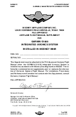
MOONEY AIRPLANE COMPANY, INC.

LOUIS SCHREINER FIELD KERRVILLE, TEXAS 78028

FAA APPROVED

AIRPLANE FLIGHT MANUAL SUPPLEMENT

FOR

GARMIN G1000

INTEGRATED AVIONICS SYSTEM

INSTALLED IN MOONEY M20R

REG. NO. _____________________________________________

SERIAL NO. ____________________________________________

This Supplement must be attached to the FAA Approved Airplane Flight

Manual when the GARMIN G1000 Integrated Avionics System is

installed in accordance with Mooney Drawing Number 950300. The in-

formation contained herein supplements and / or replaces the informa-

tion of the basic Airplane Flight Manual. For Limitations, Procedures

and Performance information not contained in this Supplement, consult

the basic Airplane Flight Manual.

FAA APPROVED

Michele M. Owsley

Manager, Aircraft Certification Office

FEDERAL AVIATION ADMINISTRATION

2601 Meacham Boulevard

Fort Worth, Texas 76137-0150

Copyright

E

2006 All Rights Reserved Mooney Airplane Company -- Louis Schreiner Field Kerrville, Texas 78028

SUPP0001B

Summary of Contents for Cessna Caravan G1000

Page 1: ...hed to the FAA Approved Airplane Flight Manual when the GARMIN G1000 Integrated Avionics System is installed in accordance with Mooney Drawing Number 950300 The in formation contained herein supplemen...

Page 2: ...OVED REVISION B 03 2006 LOG OF REVISIONS REV NUMBER PAGE NUMBER S DESCRIPTION FAA APPROVED APR VD DATE A 7 17 29 30 Add following components from Garmin G1000 Cockpit Reference Guide GDL 69A DME ADF B...

Page 3: ...2005 FAA APPROVED REVISION B 03 2006 TABLE OF CONTENTS SECTION PAGE I GENERAL 5 II LIMITATIONS 7 III EMERGENCY PROCEDURES 15 IV NORMAL PROCEDURES 21 V PERFORMANCE 27 VI WEIGHT AND BALANCE 27 VII AIRP...

Page 4: ...MOONEY M20R AFM SUPPLEMENT GARMIN G1000 INTEGRATED AVIONICS SYSTEM 4 of 33 ISSUED 11 2004 REVISION A 06 2005 FAA APPROVED REVISION B 03 2006 INTENTIONALLY LEFT BLANK...

Page 5: ...HF Communication portion of the G1000 is to enable external radio communication The primary func tion of the VOR ILS Receiver portion of the equipment is to receive and demodulate VOR localizer and Gl...

Page 6: ...e software application for prediction of GPS navigation availability may be required for oceanic and remote operations Refer to appropriate limitations for the air space you are operating in to determ...

Page 7: ...orlater FAAapproved software versions SUB SYSTEM SOFTWARE VERSION PFD 4 06 MFD 4 06 GMA 2 08 AHRS 2 03 ADC 2 05 GIA 2 08 GEA 2 04 GPS 3 01 The database version is displayed on the MFD power up page i...

Page 8: ...ta to be valid on the PFD display d When an alternate airport is required by the applicable operat ing rules it must be served by an approach based on other than GPS navigation the aircraft must have...

Page 9: ...E longitude 7 CAUTION CDI automatic source switching to the ILS on Nav 1 or 2 mustbe setto manualfor instrumentapproaches conducted with the autopilot coupled If the CDI navigation source is changed...

Page 10: ...legend for that display will change to the color of the prohibited range and will begin flashing as well MOONEY M20R Indication Red arc bar Lower prohibited range Yellow arc bar Caution range Green a...

Page 11: ...ing Reference System 1 1 1 GPS 2 1 2 If the PFD is inoperative or removed for service the MFD may be used as the PFD The MFD display mustbe operated in PFD reversion ary mode by depressing the reversi...

Page 12: ...em is not receiving airspeed input from the air data computer accom panied by a red X through the airspeed dis play ALTITUDE FAIL Display system is not receiving airspeed input from the air data compu...

Page 13: ...5 150056 1010 MIXTURE PUSH RICH 6 150056 1007 PROP PUSH INCREASE 7 150056 1008 THROTTLE PUSH INCREASE 8 150056 3017 LIGHTING DETECTION EQUIP OPT 9 150056 1009 PULL FOR ALTERNATE STATIC SOURCE 10 15005...

Page 14: ...MOONEY M20R AFM SUPPLEMENT GARMIN G1000 INTEGRATED AVIONICS SYSTEM 14 of 33 ISSUED 11 2004 REVISION A 06 2005 FAA APPROVED REVISION B 03 2006 INTENTIONALLY LEFT BLANK...

Page 15: ...to the route and phase of flight When continuing to use GPS navigation position must be verified every 15 minutes using the G1000 VOR ILS receiver or another IFR approved primary navigation system 6 C...

Page 16: ...ire checklists found in the M20R POH and appropri ate AFM supplements Electrical System Failures Alternator Failure If the Main Alternator fails indicated by the Master Warning ALT VOLTS is flashing P...

Page 17: ...LT FIELD S ALT OUT S STBY ALT S BAT S AUX PANEL S AUX OVHD S GLRSHIELD LIGHT S PFD S MFD S AHRS S ADC S ENGINE INST S STBY GYRO S ICE PROT SYS S STBY BUS BAT S COM 1 S NAV 1 GPS 1 S AUDIO S XPONDR S S...

Page 18: ...panel PUSH b AHRS FAILURE NOTE Failure of the Attitude and Heading Reference System AHRS is indicated by a removal of the sky ground presentation and a red X and a yellow AHRS FAILURE shown on the PFD...

Page 19: ...r messages fuel quantity and flow to safely complete the flight e ERRONEOUS OR LOSS OF WARNING CAUTION ANNUNCIATORS NOTE Loss of an annunciator may be indicated when engine or fuel displays show an ab...

Page 20: ...MOONEY M20R AFM SUPPLEMENT GARMIN G1000 INTEGRATED AVIONICS SYSTEM 20 of 33 ISSUED 11 2004 REVISION A 06 2005 FAA APPROVED REVISION B 03 2006 INTENTIONALLY LEFT BLANK...

Page 21: ...itten in the POH AFM DETAILED OPERATING PROCEDURES Normal operating procedures for the G1000 are described in the GAR MIN G1000 Cockpit Reference Guide and the GARMIN G1000 Pilot s Guide 1 5 NORMAL PR...

Page 22: ...initiated if the operation of the standby al ternator and emergency bus is not in satisfactory condition prior to take off BEFORE TAXI Engine Start Checklist Completed Elevator Trim Switch On Interna...

Page 23: ...ncrease RPM until the AMPS indication on the G1000 indicates a positive number BEFORE TAKEOFF Taxi Checklist Complete Parking Brake Set Fuel Selector Fullest Tank Throttle 1000 RPM Propeller High RPM...

Page 24: ...Select the other battery using the BAT 1 2 selector Ammeter CHECK Positive Charge Indication Main Battery Voltage Greater than 26 5VDC Select desired Main Battery for use during flight using BAT 1 2...

Page 25: ...instead of being pulled into it TAKEOFF NORMAL Power FULL THROTTLE 2500 RPM Mixture Check and set at top of the white arc on EGT Annunciator CHECK Engine Instruments CHECK for proper indications Lift...

Page 26: ...ULL THROTTLE 2500 RPM Mixture FULL RICH or white arc on EGT Rudder Trim As Desired Airspeed 105 KIAS CLIMB BEST ANGLE Vx Power FULL THROTTLE 2500 RPM Mixture FULL RICH Rudder Trim As Desired Airspeed...

Page 27: ...ding Reference System AHRS an Air Data Com puter ADC and the sensors and computers to process flight and en gine information for display to the pilot The system contains dual GPS receivers dual VOR IL...

Page 28: ...mergency use by pressing the DISPLAY BACKUP button on the audio panel In the com posite mode the crew alerting function remains operative but no map functions are available The Multi Function Display...

Page 29: ...ime weather information is transmitted to the aircraft via XM Satellite Radio XM WX Satellite Weather service operate in the S band frequency to provide continu ous uplink capabilities at any altitude...

Page 30: ...ch is mounted on the front of the engine It is driven by the engine crankshaft through a shear mechanism and charges the main batteries The alternator is the primary source of aircraft power and is co...

Page 31: ...recognition landing light sys tem consists of 2 lights one in each wing tip and is operated by a rocker type switch mounted in the overhead switch panel Landing and taxi lights are mounted on the wing...

Page 32: ...NG WET COMPASS COMPASS LIGHT 2A STBY GYRO 7 5A GLRSHLD LIGHT 5A ADC 5A AHRS 5A ENGINE INST 5A MFD 5A PFD NO 1 GDU1040 PFD NO 2 GDU1040 MFD GEA71 ENGINE AIRFRAME GRS77 AHRS GDC74 AIR DATA GLARE SHIELD...

Page 33: ...series aircraft Engine and electrical switches are located on the left side of the switch panel Nav strobe recognition landing and taxi light switches are lo cated on the overhead switch panel Instru...

Reviews: