


E_MH_Installation_instruction_Skycom_Skymax_CE
01/10/2016
8/26
Connection, operation and settings
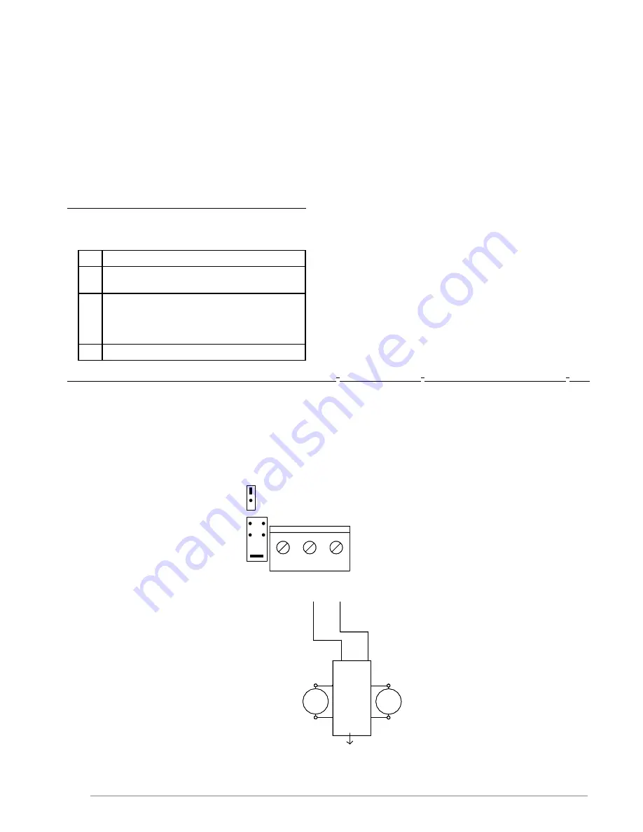
Motor (actuator)
The actuators must be connected to output terminals 2-3. The max. load is 5A.
It is possible to disable the line monitoring on the motor output. The cables can be connected in series or parallel or a
combination of these (see drawings motor and electrical schemes).
It is important to keep the right polarity. The motors of most systems must be connected via a limit switch - see electrical
scheme of the specific opening system.
See table at the end for cable sections and max. motor cable length.
Cable monitoring (line monitoring) on the motor output
The control is equipped with 3 possible settings for cable monitoring (line monitoring), which can be configured by
means of jumper J2.
a. Jumper J2 mounted in pos. “Motor line” (Setting for Skylux
®
160° CE, Skymax
®
CE old and new and Cintramax
®
CE)
Known motor: line monitoring (2-3) with double wired motor connexion.
Jumper J3 (actuator output) is set according to the number of termination resistors (27KΩ) to be detected – 1 to max. 4
lines can be detected by moving jumper J3 – this means that the cable installation between the control unit and the motors
can be established in series connection (cable connection from smoke hatch 1, further to smoke hatch 2, etc.), or parallel
connection (cable connection from each smoke hatch to the control), or a combination of these. However, as mentioned
max. 4 different lines can be detected, each of them connected to the end resistor of 27KΩ.
Jumper description
J3
Number of connected 27Kohm terminal
resistors for actuator output
J2
Chooses line monitoring through motor
terminals 2-3 (Mot Mon) or separate
wire terminals 1-3 (Ext Li Mon), or no
line monitoring when J2/J3 is removed
F1
Fuse 8A for actuator output
Line 1
1
CH
1
24V Out
Actuator
2
3
+
-
5
LIP
2
1
4
6
3
M1
24V Out
Actuator
2
1
Actuator
Motor line monitor
Ext 3 wire monitor
(line 1)
Blue
Next LIP
Brown
Blue
J2
1
J3
4
3
2
1
M2
Blue
Brown


