244
SJ82 T, SJ86 T
229040ABA
Section 5 – Procedures
Manifolds and Hydraulic Pumps
5.8 Manifolds and Hydraulic
Pumps
5.8-1 Hydraulic Brake Pressure
Adjustment
Maintaining accurate hydraulic brake pressure is
important when it comes to safe aerial platform
operation.
1.
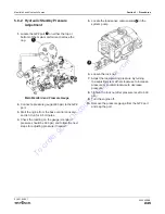
Locate the pressure gauge
1
on the brake
valve assembly.
IMPORTANT
Failure to remove the wiring may cause damage to
components downstream.
2.
Remove the wiring from two valves: axle lockout
valve
2
wires 65 and 02, and two speed valve
3
wires 45 and 02. Mark the valves to ensure
you put the wiring back in the correct positions
later.
IMPORTANT
Valve damage will occur if tightened too much.
3.
Locate the brake system pressure reducing
valve PR1
4
. Loosen the lock nut and turn the
adjustment stem gently clockwise 2 full turns.
4.
Start the engine from the platform control
console and extend the boom slightly
(approximately 12” (30 cm)) to achieve low
speed drive.
5.
Drive the MEWP forward or reverse. The
pressure gauge reading should be 400 psi. Stop
the aerial platform. Follow the next steps for
adjusting the relief valve pressure if needed. If
no adjustment is required, skip ahead to step 10.
6.
Locate the brake system pressure reducing
valve PR1 and turn the valve gently
counterclockwise to the initial position.
7.
Drive the MEWP forward or reverse. The
pressure gauge reading should be 400 psi.
8.
Stop the MEWP and adjust the pressure
reducing valve PR1 1/4 turn at a time by turning
it either clockwise to increase the pressure, or
counterclockwise to decrease the pressure.
9.
Repeat steps 7 and 8 until the brake pressure is
achieved (400 psi) then tighten the lock nut on
the brake system pressure reducing valve PR1.
10.
Reinstall the wiring in the same positions it was
removed from in step 3.
11.
Test the brake and two speed functions.
2
3
1
4
To
order go
to
Discount-Equipment.com


