background image

8. RAINGAUGES

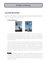
It is essential to the accurate collection of rainfall that the tipping bucket gauge should be mounted level. An
aluminium base plate is provided for this purpose, which can be pegged into soft ground, or bolted to a
permanent surface. 

8.1 Environmental Measurements Raingauge ARG100

Firstly, remove the raingauge funnel collecting top by unscrewing the 3 plastic
screws on its sides. Screw the 3 threaded pillars into the aluminium base plate
so that the ends are flush with the underside of the plate, and secure with the
locking nuts. Screw a white plastic knurled adjusting nut onto each of the
pillars, about halfway down its length. Feed the raingauge base over the 3
pillars, feed on the white spacers and the final adjusting nut on top. See
Figure 5.

Use the 6 adjusting nuts to level the raingauge base using the built-in level 

bubble as a guide and replace the raingauge funnel top.

The raingauge is fitted with 6m cable, so that it can be installed about 4m away from a 2m high 
mast. Plug and screw up (do not overtighten) the raingauge connector into the socket labelled  
RAINGAUGE on the DataHog or MiniMet logger. Run the cable down the pole and / or the guy 
ropes, securing with plastic cables to prevent movement and cable rubbing.

8.2 Rainwise Raingauge

1. It is essential to the accurate collection of rainfall that the tipping 
bucket gauge should be mounted level.

2. The raingauge is fitted with a 6m cable, so that it can be installed 
about 4m away from a 2m high mast.

3. Loosen the four screws on the outside of the raingauge and twist to 
separate the two halves of the instrument. Put the top to one side.

4. Screw the four threaded pillars into the aluminium base plate so that the ends are flush with the 
underside of the plate and secure with the four locking nuts.

5. Screw a white plastic knurled adjusting nut onto each of the pillars, about halfway down its length.

6. Feed the raingauge base over the four pillars.

19

MiniMet Installation

Summary of Contents for MiniMet

Page 1: ...MiniMet Installation Manual Iss 2 0...

Page 2: ...SCREENS FOR RH AIR TEMPERATURE 12 6 LEVELLING UNITS FOR LIGHT SENSORS 14 7 MOUNTING THE WIND SENSORS 15 7 1 Vector Wind Sensors 15 7 1 1 Single Vector Wind Sensors 16 7 1 2 Vector Anemometer plus Wind...

Page 3: ...pendix 1 List of Tools required for installation 43 Appendix 2 Concrete Bases 44 Appendix 3 Site Location 45 Appendix 4 Assembly of Mast Supplied in Sections 46 Appendix 5 Assembly of Pole Wall Mounti...

Page 4: ...own chapter some of which may not be applicable to your system The final assembly is described in Section 17 A section is included on the care and maintenance of your system please see Section 18 Sky...

Page 5: ...sors will be mounted on a central pole but a raingauge is fixed at a distance of 3 4m from the base of the pole Usually the raingauge is pegged or bolted to the ground so that the collecting rim is at...

Page 6: ...oofed building or at the apex of the roof as appropriate If there is a handrail around the roof which is sturdy enough to prevent a person falling off this could be used to clamp the 2m mast in place...

Page 7: ...may be necessary to adjust this finally Pass the guyline locking ring over the pole to about halfway If the pole has been made up of two sections make sure the locking ring is above the joining bolts...

Page 8: ...he end of each guyline and attach Adjust the guyline tautness by locking the ring into place driving the T pegs fully into the ground at the correct angle 90 to the guyline and turning the shackles to...

Page 9: ...into the ground if appropriate and turning the shackles to tighten making sure the mast pole is vertical using the spirit level 3 4 Erection of Mast on Roof Top As each installation will have differi...

Page 10: ...ws 12 x LARGE GUYLINE PEGS 1 x TEMPORARY GUYLINE SET 3 ropes and 3 small pegs The mast baseplate should be held in place by the small pegs if used on soft ground or bolted in place if used on a concre...

Page 11: ...he maximum safest extension length Extend the mast sections until the marked areas are just not visible 2 Gently finger tighten the guyline rings at the very top of the mast and at 7 5m 5m and 2 5m he...

Page 12: ...p of the lowest section can be easily reached This mast is intended to be extendable to a maximum of 10 metres Under no circumstances should the mast be extended to a position where the cross hatch ma...

Page 13: ...varied to suit the site The inner set of blocks should be between 3 5 and 5 metres from the centre and the outer set of blocks should be between 6 and 10 metres from the centre The mast fits into a s...

Page 14: ...integral RH Air temperature DataHogs or bracket for DataHogs without integral RH Air temperature Undo the 4 screws on the white protruding pillars on the flat underside of the radiation screen and us...

Page 15: ...logger and remove the base you will see the instrument case has a double skin There are four mounting holes outside the inner compartment one in each corner which are used for attaching the radiation...

Page 16: ...revent cable movement and damage from rubbing RH air temperature sensors should be mounted in a position where air may freely circulate through the radiation screen and are not near any hot or radiati...

Page 17: ...neath There are 2 more nylon bolts supplied for fixing to either a long or short arm mounting bracket The brackets have four mounting holes on the flat back plate suitable for bolting to a wall or ver...

Page 18: ...gle ball bearing which must be positioned exactly to secure the vane in place You will see a notch near the end of the spindle which must be aligned with the ball bearing just visible inside the vane...

Page 19: ...ided These can be fitted to masts up to 50 mm maximum diameter Always use plastic cable ties to prevent cable movement and rubbing 7 1 2 Vector Anemometer plus Windvane The white painted aluminium dua...

Page 20: ...nuts can now be tightened to secure the assembly to the mast 12 Plug and screw up do not overtighten the sensors connectors into the DataHog or MiniMet logger sockets marked WIND SPEED and WIND DIRECT...

Page 21: ...d over the top of the mast 10 IMPORTANT The instrument body has an N printed on the side Using a compass align the N so that it is pointing NORTH 11 When the sensor is in this position it will be meas...

Page 22: ...aingauge funnel top The raingauge is fitted with 6m cable so that it can be installed about 4m away from a 2m high mast Plug and screw up do not overtighten the raingauge connector into the socket lab...

Page 23: ...e should be mounted level 2 Using two M6 bolts line up and attach the raingauge base plate to the longarm bracket 3 On the underside of the bracket attach one washer and one nut to each bolt and tight...

Page 24: ...screw up do not overtighten the raingauge connector into the DataHog or MiniMet logger socket marked RAINGAUGE 13 Use plastic cable ties to prevent cable movement and damage from rubbing 21 MiniMet I...

Page 25: ...itable for bolting to a wall or vertical surface It is supplied as standard with a pair of V bolts washers nuts and end caps used for fixing to a pole or mast up to a maximum diameter of 50 mm See App...

Page 26: ...ugh the instrument casing is square the mounting holes are not squarely placed Tighten these four mounting screws securely but gently and replace the instrument base TAKE CARE to orientate the top cor...

Page 27: ...tilise the same element as 11 1 but the sensing element is not covered it is left exposed for a faster response The wire from the element is connected to the standard sensor cable terminating in a plu...

Page 28: ...t arched slightly down and not actually touching the dish 10 Use four plastic cable ties laced through the corresponding four holes in the dish to further secure the cable leading from the sensor 11 T...

Page 29: ...oil slurry to ensure good contact We would recommend the use of an auger which can be purchased from Skye Please see the Tensiometer manual for full details Plug and screw up do not overtighten the te...

Page 30: ...nsor consists of a float pulley and counterweight attached to a precision 1000 ohm potentiometer mounted through a gear assembly in a weatherproof housing The triangular base plate is equipped with th...

Page 31: ...he Southern Hemisphere However if the DataHog or MiniMet system also contains a light or solar radiation sensor this sensor must take priority over positional placing and must not be obscured It is ac...

Page 32: ...d and USB Serial USB converter between the RS232 socket on the MainsHog unit and a USB port of the computer Install and run SkyeLynxComms please refer to the separate manual 15 2 Mains Hog with Signal...

Page 33: ...Hog or MiniMet to the PC install the 1m datalead between the RS232 socket on the MainsHog unit and the serial port of the computer Install and run the Skye software as instructed in the manual 30 Mini...

Page 34: ...ide the GSM GPRS housing The antenna and bracket just need fixing to the mast The antenna needs to be mounted on the mast as high as possible see Appendix 15 To connect the 12V battery first locate th...

Page 35: ...e first COVER THE SOLAR PANEL Then slip the bolts around the mast within the GSM GPRS module s spacers and then attach the spacers and solar bracket The end result will be the 2 sets of bolts neatly i...

Page 36: ...cing towards the sun A barometer can be mounted next highest its orientation is not critical The light or solar radiation sensor on its long arm pole mount can now be mounted so that the top of the se...

Page 37: ...iniMet incorporating the RH and air temperature probes are usually placed opposite the light sensor to counter each other s weight The short arm pole mount on the logger means that it is possible to p...

Page 38: ...uipment for the user to make their own recalibrations using the saturated salt solution technique The radiation screen and mounting should be kept clean to ensure good air flow over the sensor tip 3 A...

Page 39: ...is calibrated and fixed at the time of manufacture As long as the physical shape or form of the wind vane and its spindle does not change i e by physical damage then the sensor calibration does not ch...

Page 40: ...le solar radiation sensor Clean radiation screen to ensure free air flow over sensors Clean and fit spares and new filter to raingauge Check total system for integrity Full telephone support PRE PAID...

Page 41: ...it within 2 working days Full telephone support CONTRACT 5 Biennial or Triennial health check service of WindHog System one site visit by engineer to undertake calibration operation check of WindHog s...

Page 42: ...just the data or if you would like a Live Display of the weather on your computer i Data only You will need SkyeLynxComms installed on the PC attached to the MiniMet Offload the data as and when you r...

Page 43: ...customers using this server will be given their own user name and password for access to their data Access to data only is provided as part of the cost of the MiniMet but a DataPlus Service which giv...

Page 44: ...3 Screwdriver 75 x 3mm parallel tip 4 Cutters 140mm 5 Screwdriver chubby flat 6 Club hammer 2 5lb 7 Allen keys 3mm 8 6 adjustable spanner 9 Compass 10 Small spirit level 11 10mm ring spanner 12 No 2 P...

Page 45: ...APPENDIX 2 CONCRETE BASE FOR A 2M MAST 44 MiniMet Installation...

Page 46: ...APPENDIX 3 SITE LOCATION 45 MiniMet Installation...

Page 47: ...APPENDIX 4 ASSEMBLY OF MAST SUPPLIED IN MORE THAN ONE SECTION 46 MiniMet Installation...

Page 48: ...APPENDIX 5 ASSEMBLY OF POLE WALL MOUNTING BRACKETS APPENDIX 6 ARG 100 RAINGAUGE BASEPLATE ASSEMBLY 47 MiniMet Installation...

Page 49: ...APPENDIX 6 RAINGAUGE BASEPLATE 48 MiniMet Installation...

Page 50: ...APPENDIX 7 MOUNTING OF GSM GPRS ENCLOSURE TO BRACKET 49 MiniMet Installation...

Page 51: ...APPENDIX 8 MOUNTING THE GSM GPRS MODULE ON THE MAST NO SOLAR PANEL 50 MiniMet Installation...

Page 52: ...APPENDIX 9 MOUNTING OF THE GSM GPRS UNIT ON THE MAST WITH A SOLAR PANEL STEP 1 51 MiniMet Installation...

Page 53: ...APPENDIX 10 MOUNTING OF THE GSM GPRS UNIT ON THE MAST WITH A SOLAR PANEL STEP 2 52 MiniMet Installation...

Page 54: ...APPENDIX 11 MOUNTING OF GSM GPRS UNIT ON THE MAST WITH A SOLAR PANEL STEP 3 53 MiniMet Installation...

Page 55: ...APPENDIX 12 TYPICAL MINIMET INSTALLATION WITH GSM GPRS 54 MiniMet Installation...

Page 56: ...APPENDIX 13 TYPICAL MINIMET INSTALLATION WITHOUT GSM GPRS 55 MiniMet Installation...

Page 57: ...APPENDIX 14 56 MiniMet Installation...

Page 58: ...APPENDIX 15 FITTING THE BATTERY COVER 57 MiniMet Installation...

Reviews: