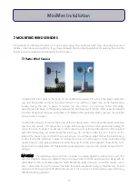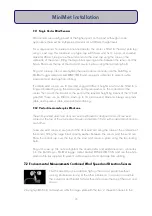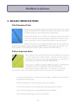
6. Now place the second dish over the pillars followed by another set of long white nylon
spacers. One on each pillar.
7. Place the third dish over the pillars and secure the assembly with the four white plastic
knurled adjusting nuts.
8. Remove the backing paper off the three sticky pads on the underside of the bottom dish.
9. Apply the sensor over the sticky pads, ensuring that the white tip is pointing towards the
centre of the dish, but arched slightly down and not actually touching the dish.
10. Use four plastic cable ties, laced through the corresponding four holes in the dish, to
further secure the cable leading from the sensor.
11. The assembly can now be sited in the desired location.
12. Push the four tent pegs, one at each end of each skid plate, firmly onto the ground to
secure the assembly.
13. Plug and screw up (do not overtighten) the sensor connector into the DataHog or MiniMet
logger sockets marked GRASS TEMPERATURE.
14. Route the cable down the mast or a guyline. Use plastic cable ties to prevent cable
movement and damage from rubbing.
25
MiniMet Installation
Summary of Contents for MiniMet
Page 1: ...MiniMet Installation Manual Iss 2 0...
Page 45: ...APPENDIX 2 CONCRETE BASE FOR A 2M MAST 44 MiniMet Installation...
Page 46: ...APPENDIX 3 SITE LOCATION 45 MiniMet Installation...
Page 47: ...APPENDIX 4 ASSEMBLY OF MAST SUPPLIED IN MORE THAN ONE SECTION 46 MiniMet Installation...
Page 49: ...APPENDIX 6 RAINGAUGE BASEPLATE 48 MiniMet Installation...
Page 50: ...APPENDIX 7 MOUNTING OF GSM GPRS ENCLOSURE TO BRACKET 49 MiniMet Installation...
Page 51: ...APPENDIX 8 MOUNTING THE GSM GPRS MODULE ON THE MAST NO SOLAR PANEL 50 MiniMet Installation...
Page 55: ...APPENDIX 12 TYPICAL MINIMET INSTALLATION WITH GSM GPRS 54 MiniMet Installation...
Page 56: ...APPENDIX 13 TYPICAL MINIMET INSTALLATION WITHOUT GSM GPRS 55 MiniMet Installation...
Page 57: ...APPENDIX 14 56 MiniMet Installation...
Page 58: ...APPENDIX 15 FITTING THE BATTERY COVER 57 MiniMet Installation...


