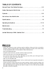
12
d.
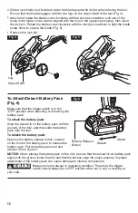
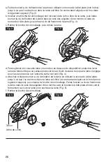
Slide a new bla
de (not included) u
nder the blade guard with its flat surface facing the tool.
Ensure that the blade engages with the two lugs on the output shaft of the tool (Fig. 4).
e.
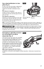
Attach and rotate the blade screw clockwise with the slot-tip screwdriver until one of the
holes in the blade is free (center aligned with the hole in the opposing housing), then insert
the lock pin.
Rotate the blade screw clockwise with the slot-tip screwdriver to tight the blade
screw firmly to secure the blade (Fig. 5).
f.
Remove the lock pin.
Fig. 4
Output Shaft
Lug
1
3
2
Fig. 5
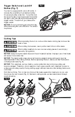
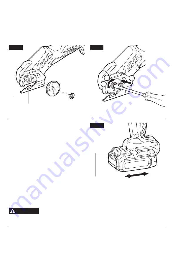
To Attach/Detach Battery Pack
(Fig . 6)
Make sure that the trigger switch is in the
”OFF” position when attaching or detaching the
battery pack.
To attach the battery pack:
Align the raised rib on the battery pack with the
grooves of the tool, and then slide the battery
pack onto the tool.
To detach the battery pack:
Depress the battery-release button, located
on the front of the battery pack, to release the
battery pack. Pull the battery pack out and
remove it from the tool.
NOTICE: When placing the battery pack on the tool, be sure that the raised rib on battery pack
aligns with the groove inside the tool and that the latches snap into place properly. Improper
attachment of the battery pack can cause damage to internal components.
WARNING
Battery tools are always in operating condition. Therefore, the
trigger
switch should always be in OFF position when not in use or carrying at
your side.
Fig. 6
Attach
Battery-Release
Button
Detach


