background image

switch is accidentally bumped when the operator is entering or exiting the skid steer with 
the engine running. 
    Always  refer  to  the  polarity  symbols  printed  on  the  top  of  the  battery.  Refer  to  the 
markings on the battery to determine the location of the negative (-) cable. If the battery 
cables are to be removed  from the battery, always remove the negative cable first and 
reinstall the negative cable last. 
    DO NOT smoke around a battery, or use anything that produces an open flame or spark 
to avoid an explosion that could result in Death or Serious Injury. 
    The 12V power source for this attachment should be connected into the  skid  steer's 
Operator Presence System that cuts the electrical power to the attachment shift valves if 
the  operator  safety  restraint  bar  is  raised  or  the  seat  switch  is  disengaged  when  the 
operator raises from the seat.   
    When using the provided joystick, route the electrical harness up to the pivot point of 
the loader arm and tie it with plastic cable ties to the inside of the loader arm to prevent 
snagging  the  harness  with  branches.  After  installing  harness,  check  that  the  harness  is 
free  from  any  tension  when  raising  and  lowering  the  loader  arm  through  its  complete 
cycle. 
    To  protect  the  operator  from  any  flying  debris,  it  is  important  that  the  skid  steer  is 
equipped with a thermoplastic polycarbonate windshield or similar.


Summary of Contents for ZABC42

Page 1: ...Skid Steer Articulating Brush Cutter OPERATOR S AND PARTS MANUAL Model ZABC42 Rev 01...

Page 2: ...e implement Before each operation of this implement check all hardware bolts nuts pins cotter pins etc for their proper location and tightness Stop the engine on the skid steer and set the brake to av...

Page 3: ...r this attachment should be connected into the skid steer s Operator Presence System that cuts the electrical power to the attachment shift valves if the operator safety restraint bar is raised or the...

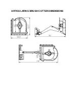
Page 4: ...ARTICULATING BRUSH CUTTER DIMENSIONS...

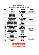
Page 5: ...ng Degree 90 8 Max Head Tilt Degree 35 9 Hydraulic Flow Required 14 20GPM 10 Max pressure of oil 2000 2500 psi 11 Direct Current Voltage DC12V 12 Check Valve CIT 03 G3 8 13 hydraulic cylinder 2 5 x1 5...

Page 6: ...to the appropriate connector on the skid steer Check the surrounding area for bystanders and clear them before starting the skid steer or attachment Before operating the attachment always visually ins...

Page 7: ...plumbing for any noticeable leaks Correct these leaks before continuing 9 Restart the skid steer With the attachment raised off the ground and the engine throttle set just above idle engage the cutter...

Page 8: ...a damaged cutting blade or material trying to be cut at too fast a pace Slow down the skid steers ground speed to see if vibration stops If it does not stop the cutter turn off the skid steer engine...

Page 9: ...pect the area to be cut and make sure it is free of any utilities rocks fence posts or any other objects that you do not want to cut or that would damage the cutter Do not enter into an area to be cut...

Page 10: ...lity of your machine and notice the terrain you are working on Raise the skid steer loader arm and tilt the cutter head to the vertical position Swing the boom to the right to access the area to be cu...

Page 11: ...r blades can be very sharp and could cause Minor or Serious Injury if mishandled Always wear protective gloves and footwear Position the cutter attachment with cutter deck in the vertical position so...

Page 12: ...grease into all required areas until you see old grease is being flushed out Investigate the location of any oil leaks and repair After every use clean off any dirt residue with a garden hose and rep...

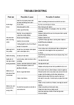
Page 13: ...the cutter height to clear exposed rock surfaces Blades breaking Excessive shock loads Avoid hitting solid objects rock steel pipes large tree stumps etc Hydraulic oil level goes down during operation...

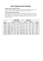
Page 14: ...n Always use grade 8 8 or better when replacing bolts METRIC BOLT TORQUE SPECIFICATIONS The following torque values are for use with metric Bolt head identification marks as per grade hardware that is...

Reviews: