37
12
EN
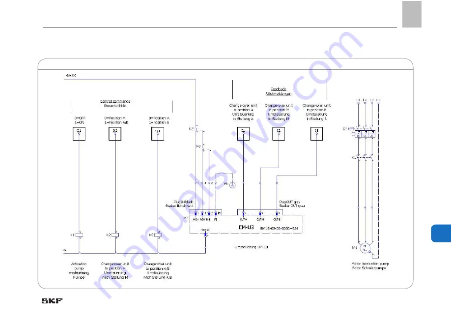
12.1 Circuit diagram EM-U3 24 V DC
Circuit diagram 24 V DC Abb. 14
12. Circuit diagrams
Page 1: ...EN Version 03 Installation instructions following machinery directive 2006 42 EC Electromotive change over device Electromotive way valve Series EM U3 WS E...
Page 2: ...horities The person empowered to assemble the technical documentation on behalf of the manufac turer is the head of standardization See manufacturer s address Furthermore the following directives and...
Page 3: ...SKF All rights reserved Manufacturer SKF Lubrication Systems Germany GmbH Walldorf Facilities Heinrich Hertz Str 2 8 DE 69190 Walldorf Phone 49 0 6227 33 0 Fax 49 0 6227 33 259 E mail Lubrication germ...
Page 4: ...rview functional description 17 3 1 Brief description EM U3 18 3 2 Brief description WS E 19 3 3 General system description 20 3 4 EM U3 as a replacement of EM U2 21 4 Technical data 22 4 1 General te...
Page 5: ...ce 33 9 3 Cleaning 33 9 4 Check for proper function 33 9 5 Check for damages 33 10 Troubleshooting 34 11 Spare parts 35 12 Circuit diagrams 37 12 1 Circuit diagram EM U3 24 V DC 37 12 2 Flow diagram E...
Page 6: ...which warn of specific dangers to persons material assets or the environment next to all safety in structions in these operating instructions Please read these instructions thor oughly and heed the w...
Page 7: ...per hour if appl if applicable rpm revolutions per minute hp horse power a a r as a rule in inch Conversion factors incl including Length 1 mm 0 03937 in K Kelvin Area 1 cm 0 155 sq in kg kilogram Vo...
Page 8: ...s in proper technical condition and according to the information in these instructions Technical personnel must familiar ize themselves with the functions and operation of the product The specified as...
Page 9: ...nnel and the prohibition against employing non qualified personnel are laid down in DIN VDE 0105 and IEC 364 Relevant country specific definitions of qualified technical personnel apply for coun tries...
Page 10: ...is pressurized during operation It must be depressur ized before starting assembly maintenance or repair works WARNING Electric shock Working on products not discon nected from the power supply may c...
Page 11: ...ct Undertake drilling at non critical non load bearing parts only Fuses must not be bypassed Always re place fuses by such of the same type Other units of the superior machine must not be damaged or i...
Page 12: ...e usage wrong or improper assembly electrical connection wrong control by the operator s PLC controller contaminated or unsuitable lubricants improper or late response to malfunctions unauthorized mod...
Page 13: ...spilled or leaked lubricant Be careful when connecting or disconnecting hydraulic connections Promptly apply suitable binding agents to remove the leaked or spilled lubricant Follow the operational in...
Page 14: ...ironmental aspects must also be considered ATTENTION Observe the instructions from the machine manufacturer regarding the lubricants to be used The amount of lubricant required at the lube point is sp...
Page 15: ...e cases there may be lubri cants whose properties are within permis sible limit values but whose other charac teristics render them unsuitable for use in centralized lubrication systems For exam ple s...
Page 16: ...bstances that require special precaution ary measures during transport storage and processing Consult the safety data sheet from the lubricant manufacturer for information regarding transport storage...
Page 17: ...e right and left side 5 Electrical input 6 Electrical output 7 Position indicator of change over cartridge below protective cap 8 Motor 9 Power supply board only 230 VAC 10 Control printed circuit boa...
Page 18: ...lubrication system s compo nents life thanks to lower pressure load and reduces the bleeding of the lubricant The current position of the change over cartridge is indicated by the position of the notc...
Page 19: ...owerful shut off and way valve Here the middle position M cannot be used Fig 7a 3 2 way valve Port B closed Fig 7b 3 2 way valve Port R closed Fig 7c 2 2 way valve Ports B and R closed Brief descripti...
Page 20: ...ng valve electromotive change over device 2 EM U3 resp way valve WS E to connect pres sure line P 3 relief line R 4 and the two main lines A 5 and B 6 Downstream SKF Duoflex metering devices 7 are int...
Page 21: ...cally see connection diagrams Put superior machine into operation again Carry out the function control of the EM U3 as described in these instructions Dispose of the EM U2 in an environmen tally sound...
Page 22: ...tallation position any Change over time 5 sec max Minimum distance between 2 switching pulses 2 sec min Sound pressure level 70 dB A Weight 24 V DC approx 12 kg 230 VAC approx 13 kg Lubricants NLGI I...
Page 23: ...ainst reverse polarity short circuit proof non isolated Power consumption 20 W 20 W Length of connection cable with cable cross section 1 0 mm2 14 m 35 m Length of connection cable with cable cross se...
Page 24: ...ith housing C 20 Nm 2 Nm According to the type of installation machine or base plate the EM U3 WS E is fastened by suitable means e g screws dowels on the four F points In case of through holes screws...
Page 25: ...of the applied directives 2014 30 EU Electromagnetic compatibility 2011 65 EU RoHS II Directive on the restriction of the use of certain hazardous sub stances in electrical and electronic equipment R...
Page 26: ...Protect the product against mechanical influences such as im pacts There are no restrictions for land sea or air transport Mark returns on the pack aging as follows Marking of returns Fig 7 5 3 Storag...
Page 27: ...g material until any dis crepancies are resolved Note Technical data see chapter 4 6 2 Attachment Protect the product against humidity and vibration and install it in an easily accessible position to...
Page 28: ...nance work or for a possible disassembly of the product by leaving a free space of at least 50 mm into each direction in addition to the stated dimensions 180 136 125 P A C D D B R 110 16 198 5 113 5...
Page 29: ...nection conditions and legal pre scriptions e g DIN VDE have to be observed 6 5 Assignment of the power supply 6 4 Electrical connection 6 6 Assignment of the power supply The required cross section...
Page 30: ...sure of the annular gear unit the admissible tem peratures and the lubricants to be supplied Furthermore the lubrication line system must be protected against inadmissibly high pressure Before the ass...
Page 31: ...nnection of the control and power supply lines as well as the correct connection of the tube lines com missioning of the EM U3 WS E shall be carried out by qualified personnel following the start up p...
Page 32: ...ctions 8 3Shutdown and disposal In case of final shutdown follow the appli cable rules and regulations on disposal The product can also be returned to the manu facturer for proper disposal in which ca...
Page 33: ...he actual conditions of application 9 3 Cleaning Thorough cleaning of all outer surfaces Do not use aggressive cleaning agents Interior cleaning is required only in case of accidental use of contamina...
Page 34: ...change over procedure is triggered Interruption of the control line End of line pressure switch does not give any signal Check electrical lines to and from the EM U3 WS E Check end of line pressure sw...
Page 35: ...518 34960 1 2a Control pcb 24 V DC Part no 518 34960 2 or 2b Control pcb 230 V AC Part no 518 34960 3 3 Power supply board 230 V AC Part no 518 34960 7 4 5 pole black device connection Part no 664 85...
Page 36: ...DC version Connections B and R closed EMU 22 66 0000 1KF WS E 2 2 way valve 230 VAC version Connections B and R closed EMU 32 06 0000 924 WS E 3 2 way valve 24 V DC version Connection R closed EMU 32...
Page 37: ...37 12 EN 12 1 Circuit diagram EM U3 24 V DC Circuit diagram 24 V DCAbb 14 12 Circuit diagrams 12 Circuit diagrams...
Page 38: ...38 EN 12 2 Flow diagram EM U3 24 V DC Signals EM U3 24 V DC Fig 15 12 Circuit diagrams...
Page 39: ...39 12 EN 12 3 Circuit diagram EM U3 230 V AC Circuit diagram 230 VAC Fig 16 12 Circuit diagrams...
Page 40: ...40 EN 12 4 Flow diagram EM U3 230 V AC Signals EM U3 230 VAC Fig 17 12 Circuit diagrams...
Page 41: ...Notes...
Page 42: ...rom 3 D computer modelling to advanced condition monitoring and reliability and asset management systems A global presence provides SKF customers uniform quality standards and worldwide product availa...