SKF Ecomag Installation, Operation And Maintenance Manual Download Page 7

Technical Instructions

Linear drive Ecomag

Magnetic – The Linear Drives Company™ 

page 6/10

4

Operation

4.1

Controlling an actuator

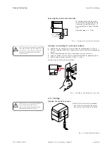
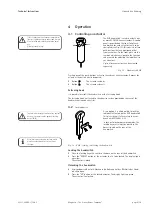
The EHE handswitch is used to actuate one
or more ECOMAG linear actuators. A control
panel is provided on the front foil of each
handswitch for each actuator that is to be
controlled (see Fig. 12). This consists of two
push-buttons that are positioned offset
from each other. On the front plate are the
symbols which are assigned to the function
and are used for adjusting the individual lin-
ear actuators.

Up to 4 linear actuators can be actuated
separately.

Fig. 12 – Handswitch EHE

Pressing one of the push-buttons activates the relevant linear actuator. It moves for
as long as the button is held depressed.

Button 

The actuator extends

Button 

The actuator retracts
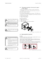
Fastening hook

It is possible to retrofit the handswitch with a fastening hook. 

The fastening hook is attached to the adhesive surface provided on the rear of the
handswitch using adhesive film. 
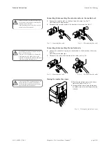
4.2

Locking device

As an option, it is also possible to lock the
individual actuators on the EHE handswitch.
This gives the unit failure safety in accor-
dance with EN 60601-2-38.

In Lock or Unlock programming mode, the
locking key must always be placed in the
bores situated on the rear of the
handswitch.

Fig. 13 – EHE.. locking / unlocking the handswitch

Locking the handswitch

Place the locking key with cam into the bore on the rear of the handswitch.

Press the "DOWN" button of the actuator that is to be locked. The display lights
up yellow. 
The actuator is locked.

Unlocking the handswitch

Verriegelungsschlüssel mit Nocken in die Bohrung auf der Rückseite des Hand-
schalters legen.

Press the "UP" button of the locked actuator. The display lights up green. 
The actuator is unlocked.

AB

AUF

If the feed speed of the linear actuator dimin-
ishes, or it no longer works under load, it must
be uninstalled immediately and taken out of
use. 
Risk of personal injury!

To avoid inadvertent activation of the control
device, we recommend the optional locking
device (EHE3).

After locking or unlocking, the locking key
must be removed and the set functions
checked.

L5311,2400E.1/12.03

Summary of Contents for Ecomag

Page 1: ... before installing operating or maintaining this actuator Failure to follow safety precautions and instructions could cause actuator failure and result in serious injury death or property damage Installation operation and maintenance manual ...

Page 2: ...Controlling an actuator 6 4 2 Locking device 6 4 3 Emergency lowering in the event of a power failure option 7 4 4 Rapid adjustment optional 7 5 Maintenance and Care 9 5 1 Maintenance 9 5 2 Care 9 5 3 Disposal 9 5 4 Liability 9 5 5 Technical data 10 5 6 Troubleshooting 10 Reference standards EN 60601 1 EN 60601 1 2 EN 60601 2 38 EN 60335 UL 2601 Magnetic Elektromotoren AG Oristalstrasse 97 CH 4410...

Page 3: ...the motor s rotational movement into a linear movement through the threaded spindle s rotation being transferred to a pushing tube via a special nut The stroke is limited by built in limit switches The power is supplied via an attachable or externally fitted SEM 1 control unit The control unit consists of a control box housing the transformer the converter up to 4 motor socket connections and a so...

Page 4: ... all mounting positions are possible provided the following points are noted If the control unit is plugged in only the mounting positions shown in Fig 1 from 0 to 90 are permitted If an overhang arrangement is used the control unit must also be fixed in position with cable ties The control unit can otherwise work itself loose Fig 1 Mounting positions Mounting the control unit on the actuator ECO ...

Page 5: ...using the wrench 5 Screw the contact washer 3 and nut 4 onto the thread of the grounding bolt 1 Tighten with the torque wrench to 1 5 Nm 1 8 Nm The cable is uninstalled in the reverse order Fig 5 Installing uninstalling the earth cable 3 4 Startup Opening the control box cover Gently lift the nose with a screwdriver and at the same time push the control box cover in the direction of the arrow Fig ...

Page 6: ...osing the control box cover Move the control box cover in the direc tion of the arrow see Fig 11 The control box cover is only closed once an audible click of the locking mechanism is heard Fig 11 Closing the control box cover 1 2 1 2 You should ensure that the handswitch cable plug is inserted correctly If the front film is damaged i e allowing liq uid to penetrate the handswitch must be replaced...

Page 7: ... adhesive film 4 2 Locking device As an option it is also possible to lock the individual actuators on the EHE handswitch This gives the unit failure safety in accor dance with EN 60601 2 38 In Lock or Unlock programming mode the locking key must always be placed in the bores situated on the rear of the handswitch Fig 13 EHE locking unlocking the handswitch Locking the handswitch Place the locking...

Page 8: ... to manually lower the head or foot of the bed further option When installing an actuator with rapid adjustment function a warning notice Fig 13 in accordance with EN 60601 1 Section 6 3c and 6 4 must be attached clearly to the end product insofar as the end application is subject to this standard Fig 13 Warning notice for rapid adjustment Magnetic AG Liestal recommends that the batteries be repla...

Page 9: ...ted as shown in Figs 14 and 15 Fig 16 Pushing the head or foot of the bed downwards After a rapid lowering action the clamping lever must be in closed position before the linear actuator is used again The emergency lowering mechanism must not be treated with oil grease or any other lubri cating substance since this can lead to it be coming dangerously easy to move It must be ensured that no object...

Page 10: ...nection device IP X0 Handswitch IP X6 und IP X7 Clean after use in order to avoid the accretion of residues The actuator may be cleaned with a damp cloth and water Add a little isopropyl alco hol if necessary 5 3 Disposal The actuators and control unit components may be returned to Magnetic Liestal AG for disposal 5 4 Liability In every case the owner or operator of the unit shall be liable for it...

Page 11: ... running noise Motor gears or Return the actuator nuts faulty immediately to the Magnetic Service Department Actuator only runs in Cut off faulty Return the actuator one direction to the Magnetic Service Department Control device faulty Replace the control device Control unit faulty Replace the control unit Control unit not Control unit not Plug the mains cable in working plugged in Control unit f...

Reviews: